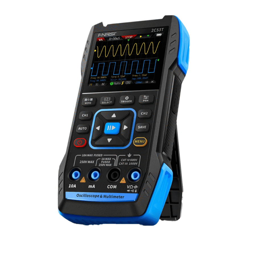
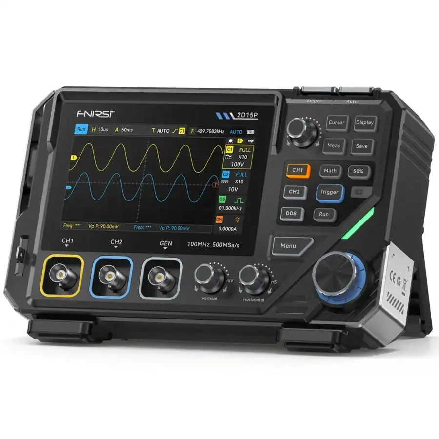
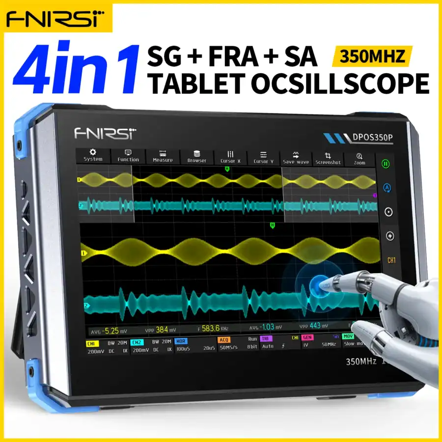
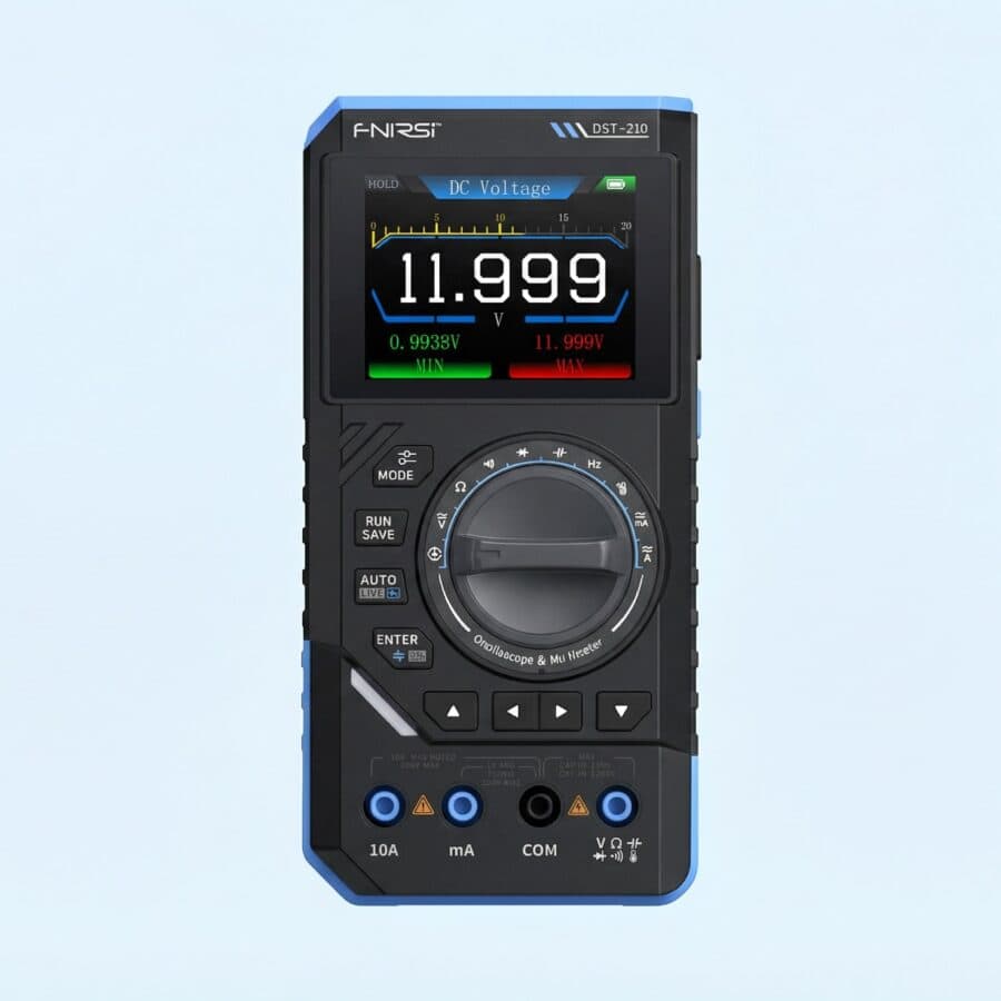
Multi-channel oscilloscopes capture four or more signals simultaneously on separate inputs.
These instruments display multiple waveforms together, revealing timing relationships and signal interactions that dual-channel oscilloscopes cannot show.
FNIRSI multi-channel oscilloscopes provide four independent input channels with bandwidth up to 100MHz per channel. Each channel operates with its own vertical controls for scale and position. Colour-coded traces distinguish signals clearly on shared displays.
Complex circuits require multiple simultaneous measurements. Power rails, clock signals, data lines, and control outputs interact in ways that only become visible when viewed together. Multi-channel oscilloscopes make these relationships measurable.
Why Multiple Channels Matter
Timing analysis requires viewing related signals together. Clock and data relationships in digital circuits depend on precise timing. Four channels let you view clock, data input, data output, and enable signals simultaneously to verify proper operation.
Signal path tracing follows signals through circuit stages. Input, intermediate, and output waveforms displayed together show how each stage affects the signal. Distortion, delay, and amplitude changes become visible across the processing chain.
Differential measurement uses two channels to show voltage between arbitrary points. Standard single-ended measurements reference everything to ground. Paired channels measure floating signals like motor drives and bridge circuits safely.
Trigger flexibility improves with more channels. Trigger on one signal while viewing others. Complex trigger conditions combine multiple channel states to capture specific events in busy systems.
Who Uses Multi-Channel Oscilloscopes?
Digital designers verify timing relationships between clock and data signals. Setup time, hold time, and propagation delay measurements require simultaneous capture of related signals. Four channels suit most synchronous digital analysis.
Embedded developers debug microcontroller systems with multiple communication interfaces. View SPI clock, MOSI, MISO, and chip select together to verify protocol operation. I2C, UART, and other interfaces benefit similarly from multi-channel visibility.
Power supply designers monitor multiple rails simultaneously. Digital circuits often require 1.8V, 3.3V, and 5V supplies operating together. Viewing all rails during load transients reveals supply interaction and sequencing behaviour.
Motor control engineers analyse drive signals and feedback together. PWM drive signals, current sense outputs, and position feedback all relate to motor performance. Multi-channel capture shows the complete control loop.
Audio engineers measure stereo signals and compare left and right channels. Phasing, balance, and crosstalk become visible when both channels display together. Four channels allow input and output comparison simultaneously.
Students learning electronics build understanding of circuit interactions. Seeing how signals relate develops intuition that single-channel measurements cannot provide. Multi-channel oscilloscopes accelerate learning for complex systems.
Multi-Channel vs Dual-Channel Oscilloscopes
Dual-channel oscilloscopes handle most basic measurement tasks. Simple circuits with one or two signals of interest measure perfectly well with two channels. Most hobbyist projects fall into this category.
Four channels become valuable when three or more signals must appear together. Serial buses, state machines, and multi-stage circuits benefit from additional channels. The extra capability costs more but saves time on complex debugging.
Channel count affects instrument size and price. Dual-channel handheld oscilloscopes maintain compact portability. Four-channel instruments typically require benchtop oscilloscope form factors with larger displays.
Consider your typical measurement scenarios. If you frequently wish for more channels during debugging, a four-channel upgrade saves reconnection time and captures events you might otherwise miss.
Key Specifications to Consider
Channel count should match your measurement complexity. Four channels suit most multi-signal applications. Higher channel counts exist but rarely appear in budget instruments.
Bandwidth per channel determines measurement accuracy for each input. Verify that all channels share the same bandwidth rating. Some instruments reduce bandwidth when all channels operate simultaneously.
Sample rate distribution may divide among active channels. A 1GSa/s oscilloscope might provide 1GSa/s on one channel or 500MSa/s per channel when using two. Check specifications for your intended channel usage.
Memory depth per channel affects capture duration at full sample rate. Shared memory divides among active channels on some instruments. Dedicated memory per channel maintains capture capability regardless of channel count.
Display clarity matters more with multiple traces. Larger screens accommodate four waveforms without crowding. Colour differentiation must remain visible when traces cross and overlap.
Independent controls should allow separate vertical scale and position for each channel. Ganged controls limit flexibility when signals have different amplitudes.
Measurement Applications
Serial bus decoding interprets communication protocols automatically. Four channels capture clock and data lines together while the oscilloscope decodes I2C, SPI, UART, and other protocols into readable data.
Power sequencing verification confirms supplies start in correct order. Boot sequences and power-on behaviour require multiple supply rails to reach specified levels in defined sequences. Multi-channel capture documents actual sequencing.
Propagation delay measurement shows signal timing through circuit stages. Trigger on the input signal while viewing outputs at each stage. Cursor measurements reveal delay through each section.
Cross-channel triggering captures events based on conditions across multiple signals. Trigger when specific combinations of channel states occur. This isolates rare events in complex systems.
Built-In Analysis Features
Waveform math combines channels mathematically. Add channels to see composite signals. Subtract channels for differential measurement. Multiply channels for power calculation on voltage and current waveforms.
FFT analysis shows frequency content of captured signals. Apply FFT to any channel to identify harmonics, noise sources, and signal components. Compare spectra across channels to locate interference sources.
Automatic measurements calculate parameters for all displayed channels. Frequency, amplitude, rise time, and duty cycle appear for each active channel simultaneously.
Cursor measurements provide manual timing and amplitude readings. Multi-channel cursors measure timing between events on different channels precisely.
Pair With Other Test Equipment
Complete your measurement capability with complementary instruments. A digital multimeter provides quick static measurements alongside dynamic oscilloscope analysis.
Signal sources for testing require waveform generation. Oscilloscopes with signal generators include built-in waveform outputs for stimulus-response measurements.
Quality probes maximise measurement accuracy on all channels. Oscilloscope probes matched to your oscilloscope bandwidth ensure each channel performs to specification.
Power your circuits under test with controlled supplies. Bench power supplies provide adjustable voltage and current while you monitor circuit behaviour across multiple channels.
UK Delivery and Support
Orders ship from our UK warehouse within 1-2 business days. Royal Mail delivers to most UK addresses in 24-48 hours.
Every multi-channel oscilloscope includes a 12-month guarantee and 60-day easy return period. UK consumer protection applies to every purchase, with our policies fully compliant with Distance Selling Regulations. Customer service responds within 1 business day.
Every oscilloscope we sell is genuine FNIRSI equipment with full manufacturer warranty coverage.
Shop now to find the multi-channel oscilloscope that matches your measurement requirements.
Frequently Asked Questions
Where can I find a budget multi-channel oscilloscope?
FNIRSI multi-channel oscilloscopes deliver four-channel capability at accessible prices. Our range includes instruments with bandwidth up to 100MHz per channel and sample rates suitable for digital and analogue circuit analysis. Features include serial bus decoding, waveform math, and automatic measurements. All models ship from our UK warehouse with fast Royal Mail delivery, 12-month guarantee, and 60-day easy returns.
Do I need four channels or are two channels enough?
Two channels handle most basic electronics work including simple circuit debugging, audio testing, and single-bus communication analysis. Four channels become valuable when you need to view three or more related signals together. Serial bus debugging, power supply monitoring, and timing verification across multiple signals benefit significantly from additional channels. Consider upgrading to four channels if you frequently reconnect probes to view different signals during the same debugging session.
Does sample rate divide among channels?
Sample rate behaviour varies by oscilloscope design. Some instruments provide full sample rate on each channel independently. Others share total sample rate among active channels, reducing per-channel rate as you enable more inputs. Check specifications carefully for sample rate in different channel configurations. FNIRSI oscilloscope specifications indicate sample rate behaviour for single and multi-channel operation so you know exactly what capability each channel provides.