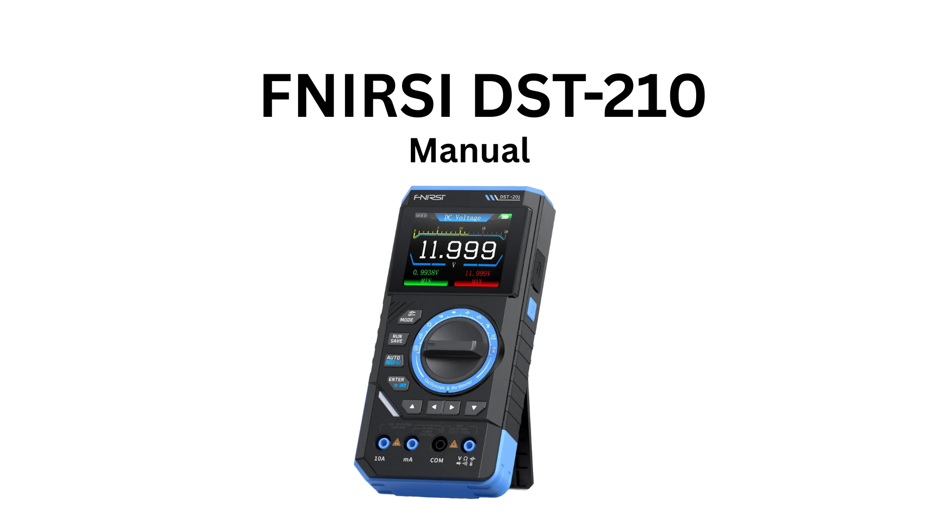
FNIRSI DST-210 User Manual
Multifunctional Oscilloscope Multimeter
Version 1.2
Table of Contents
- 1. Safety Requirements
- 2. Product Overview
- 3. Technical Specifications
- 4. Operation Guide
- 5. Quick Start Guide
- 6. Troubleshooting
- 7. Maintenance
- 8. Contact Us
- 9. Warranty Information
1. Safety Requirements
1.1 Environmental Requirements
Precautions:
- Avoid high temperature, open flames, corrosive gases, humid or dusty environments to prevent equipment failure.
- For your personal safety, use the test leads provided with the meter. Before use, inspect and ensure they are in good condition.
- Use the correct input terminals, functions, and ranges for measurements. Do not exceed the specified input limits for each range to prevent damage to the meter.
Keep Away From:
- Heaters: Avoid overheating or fire risk
- Water, chemicals, solvents: Leakage may damage equipment or cause fire
- Strong magnetic devices: Prevent magnetic field interference with normal operation
Disposal:
Do not dispose of old batteries or equipment with household waste. Dispose according to national or local regulations.
2. Product Overview
The DST-210 is a comprehensive multifunctional device launched by FNIRSI, integrating oscilloscope and multimeter capabilities into one portable unit.
Oscilloscope Features:
- Bandwidth: 10 MHz
- Sample Rate: 100 MSa/s
- Display: 2.8-inch TFT color screen with clear, intuitive interface
- Triggering: Edge trigger, auto/normal/single modes
- Measurements: Automatic measurement of frequency, period, amplitude, peak-to-peak, effective value, duty cycle, and more
- Waveform Storage: Save and recall waveforms
- USB Data Export: Transfer data to PC via USB connection
Multimeter Features:
- Comprehensive Functions:
- AC/DC Voltage measurement
- AC/DC Current measurement
- Resistance, Capacitance
- Diode test / Continuity test
- Frequency, Temperature
- Data Hold function
- LIVE wire detection (live/neutral)
- Record mode and automatic measurement
- Protection: Overload protection and low battery indication
Portable Design:
- Display: 2.8-inch TFT color screen
- Battery: Built-in high-capacity rechargeable lithium battery (3000 mAh)
- Battery Life: Supports long standby time (10 hours)
- Design: Compact and lightweight, suitable for mobile use
The FNIRSI DST-210 provides users with powerful, flexible functionality and a portable operating experience. It is an ideal multifunctional instrument for professionals, factories, schools, hobbyists, and home use.
2.1 Product Operation Diagram
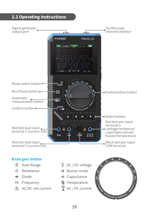
Front Panel Controls:
- Mode Switch Button: Switch between oscilloscope and multimeter modes
- Rotary Dial Selector: Select measurement function
- Automatic Measure Key: Enable automatic measurements
- Run/Pause Button: Start/stop waveform acquisition
- Confirm Button: Confirm selections
- Selection Key: Navigate menu options
Rotary Dial Positions:
- AUTO: Automatic range
- Ω (Ohm): Resistance measurement
- Diode: Diode test
- Frequency: Frequency measurement
- mA: AC/DC milliamp current
- V: AC/DC voltage
- Buzzer: Continuity test (with buzzer)
- Capacitor: Capacitance measurement
- Temperature: Temperature measurement
- A: AC/DC current (up to 10A)
Connectors:
- COM Jack: Common terminal (black lead)
- V/Ω Jack: Voltage/Resistance terminal (red lead)
- mA Jack: Milliamp current terminal
- 10A Jack: High current terminal (up to 10A)
- BNC Input: Oscilloscope signal input
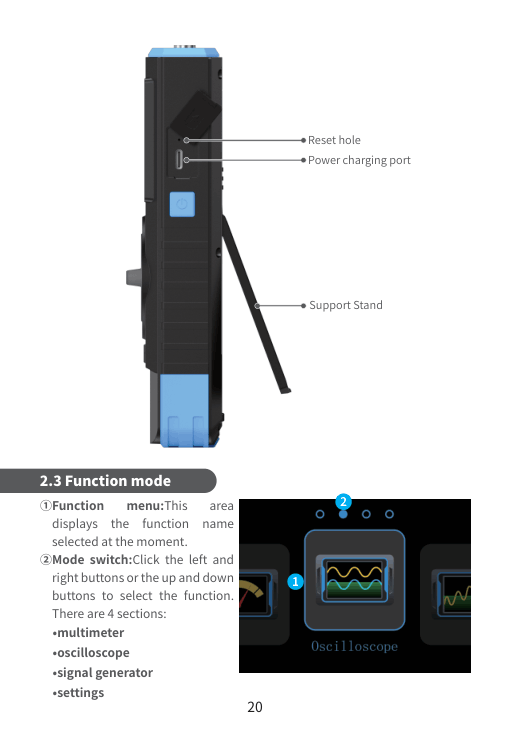
- Type-C Port: USB charging port (5V/1A)
- Reset Hole: Firmware reset button
Additional Features:
- Built-in kickstand for hands-free viewing
- LED indicators for power and charging status
3. Technical Specifications
Oscilloscope Specifications:
Bandwidth: 10 MHz (-3 dB)
Input Channels: 1 channel (BNC connector)
Sample Rate: 100 MSa/s (single-shot)
Vertical Sensitivity: 50 mV/div – 50 V/div (1-2-5 steps)
Input Impedance: 1 MΩ // 20 pF
Maximum Input Voltage: 400V (DC + AC peak)
Vertical Resolution: 8 bits
Timebase Range: 100 ns/div – 100 s/div
Trigger Modes: Auto, Normal, Single
Trigger Source: CH1
Trigger Types: Edge (rising/falling)
Record Length: 2048 points
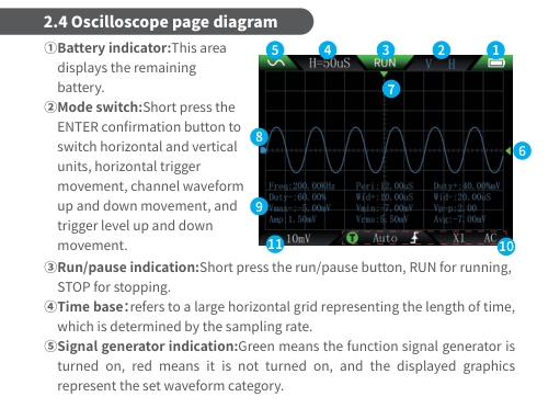
Automatic Measurements:
- Frequency (Hz)
- Period (s)
- Peak-to-Peak Voltage (Vpp)
- RMS Voltage (Vrms)
- Maximum Voltage (Vmax)
- Minimum Voltage (Vmin)
- Duty Cycle (%)
Multimeter Specifications:
DC Voltage: 0 – 600V, Accuracy: ±(0.5% + 3 digits)
AC Voltage (True RMS): 0 – 600V, Accuracy: ±(1.0% + 5 digits)
DC Current (mA): 0 – 600 mA, Accuracy: ±(1.0% + 3 digits)
AC Current (mA): 0 – 600 mA, Accuracy: ±(1.5% + 5 digits)
DC Current (A): 0 – 10A, Accuracy: ±(1.5% + 5 digits)
AC Current (A): 0 – 10A, Accuracy: ±(2.0% + 5 digits)
Resistance: 0 – 60 MΩ, Accuracy: ±(1.0% + 3 digits)
Capacitance: 0 – 10 mF, Accuracy: ±(3.0% + 5 digits)
Frequency: 10 Hz – 10 MHz, Accuracy: ±(0.1% + 2 digits)
Duty Cycle: 1% – 99%, Accuracy: ±(1% + 1 digit)
Temperature (K-type): -20°C – 400°C, Accuracy: ±(2.0% + 3°C)
Diode Test: 0 – 2V, Accuracy: ±(1% + 2 digits)
Continuity Test: < 30 Ω, Buzzer alert
General Specifications:
Display: 2.8-inch TFT LCD (320×240)
Battery: 3000 mAh lithium-ion rechargeable
Battery Life: Approx. 10 hours (typical use)
Charging Port: Type-C USB (5V/1A)
Charging Time: Approx. 3 hours
Data Storage: Internal memory for waveform storage
USB Interface: Type-C (data transfer to PC)
Operating Temperature: 0°C to 40°C
Storage Temperature: -20°C to 60°C
Humidity: < 80% RH (non-condensing)
Dimensions: 148 mm × 73 mm × 30 mm
Weight: Approx. 200g
4. Operation Guide
4.1 Oscilloscope Mode Operation
Basic Operation:
Step 1: Power On
- Press and hold power button for 2-3 seconds
- Device displays startup screen
Step 2: Select Oscilloscope Mode
- Press MODE button to switch to oscilloscope mode
- Screen displays oscilloscope interface with grid
Step 3: Connect Signal
- Connect BNC probe to oscilloscope input
- Connect probe tip to circuit under test
- Connect probe ground clip to circuit ground
Step 4: Adjust Display
- Use UP/DOWN keys to adjust vertical scale (V/div)
- Use LEFT/RIGHT keys to adjust timebase (s/div)
- Press AUTO button for automatic setup
Step 5: Trigger Settings
- Press MENU to access trigger settings
- Select trigger mode: Auto, Normal, or Single
- Adjust trigger level using UP/DOWN keys
- Choose trigger edge: Rising or Falling
Step 6: Measurements
- Press AUTO MEASURE button
- Display shows automatic measurements: Frequency, Period, Vpp, Vrms, Vmax, Vmin, Duty cycle
Step 7: Save Waveform
- Press MENU → Save
- Select memory location (1-10)
- Confirm to save current waveform
Step 8: Recall Waveform
- Press MENU → Recall
- Select saved waveform from list
- Press CONFIRM to load
4.2 Multimeter Mode Operation
Voltage Measurement (AC/DC):
- Turn rotary dial to V position
- Connect red lead to V/Ω jack, black lead to COM jack
- Press MODE to select AC or DC voltage
- Connect probes across the voltage source
- Read measurement on display
Current Measurement (AC/DC):
For mA range (0-600 mA):
- Turn rotary dial to mA position
- Connect red lead to mA jack, black lead to COM jack
- Press MODE to select AC or DC current
- Connect meter in series with circuit
- Read measurement on display
For A range (0-10A):
- Turn rotary dial to A position
- Connect red lead to 10A jack, black lead to COM jack
- Press MODE to select AC or DC current
- Connect meter in series with circuit
- Read measurement on display
⚠ Do not measure > 10A or use for > 10 seconds continuously
Resistance Measurement:
- Turn rotary dial to Ω position
- Connect red lead to V/Ω jack, black lead to COM jack
- Disconnect power from circuit being tested
- Connect probes across resistor
- Read resistance value on display
Capacitance Measurement:
- Turn rotary dial to capacitor position
- Connect red lead to V/Ω jack, black lead to COM jack
- Discharge capacitor completely before testing
- Connect probes to capacitor terminals
- Wait for reading to stabilize (may take several seconds)
- Read capacitance value on display
Diode Test:
- Turn rotary dial to diode position
- Connect red lead to V/Ω jack, black lead to COM jack
- Connect red probe to anode, black probe to cathode
- Forward voltage drop displayed (typically 0.4-0.7V for silicon)
- Reverse connection shows ‘OL’ (open) for good diode
Continuity Test:
- Turn rotary dial to buzzer position
- Connect red lead to V/Ω jack, black lead to COM jack
- Touch probes to both ends of circuit path
- Buzzer sounds if resistance < 30Ω (continuity)
- Display shows resistance value
Frequency Measurement:
- Turn rotary dial to frequency position
- Connect red lead to V/Ω jack, black lead to COM jack
- Connect probes to signal source
- Display shows frequency (Hz, kHz, or MHz)
- Duty cycle also displayed (if square wave)
Temperature Measurement:
- Turn rotary dial to temperature position
- Connect K-type thermocouple to meter
- Place thermocouple probe at measurement point
- Wait for reading to stabilize
- Read temperature in °C or °F
Live Wire Detection:
- Turn rotary dial to AUTO position
- Hold meter near AC power wire (do not touch)
- Display indicates LIVE or NEUTRAL wire
- LED indicator also shows status
Data Hold Function:
- Press HOLD button to freeze current reading
- ‘HOLD’ indicator appears on display
- Press HOLD again to resume normal operation
5. Quick Start Guide
Getting Started:
Step 1: Unpack and Inspect
Check package contents:
- DST-210 main unit
- BNC oscilloscope probe
- Test leads (red and black)
- K-type thermocouple
- USB Type-C charging cable
- User manual
Inspect for any damage from shipping
Step 2: Initial Charging
- Connect USB Type-C cable to meter and power adapter
- Charge for 3 hours before first use
- LED indicator shows charging status
- Red LED: Charging
- Green LED: Fully charged
Step 3: Power On
- Press and hold power button for 2-3 seconds
- Display lights up with FNIRSI logo
- Device enters default mode
Step 4: First Measurement
Multimeter Mode:
- Turn dial to desired function
- Connect appropriate test leads
- Perform measurement
Oscilloscope Mode:
- Press MODE button to switch to scope
- Connect BNC probe
- Press AUTO for automatic setup
- View waveform on screen
6. Troubleshooting
Device won’t power on
Possible Cause: Battery dead
Solution: Charge for 30 minutes
Possible Cause: Power button held insufficient time
Solution: Hold button 2-3 seconds
No waveform display
Possible Cause: No signal input
Solution: Check probe connection
Possible Cause: Wrong V/div scale
Solution: Press AUTO button
Possible Cause: Trigger not set
Solution: Adjust trigger level
Multimeter shows ‘OL’
Possible Cause: Open circuit
Solution: Check connections
Possible Cause: Range too low
Solution: Change to higher range
Possible Cause: Test lead broken
Solution: Replace test leads
Inaccurate readings
Possible Cause: Low battery
Solution: Charge battery
Possible Cause: Needs calibration
Solution: Contact service center
Possible Cause: Wrong function
Solution: Check dial position
Display is dim
Possible Cause: Low battery
Solution: Charge battery
Possible Cause: Brightness low
Solution: Adjust in settings menu
Won’t charge
Possible Cause: Cable damaged
Solution: Replace USB cable
Possible Cause: Adapter issue
Solution: Try different adapter
Possible Cause: Port dirty
Solution: Clean Type-C port
Freezes or crashes
Possible Cause: Software error
Solution: Press reset button
Possible Cause: Memory full
Solution: Delete saved waveforms
7. Maintenance
Regular Maintenance:
Cleaning:
- Power off device before cleaning
- Wipe display with soft, dry cloth
- Do not use chemical solvents or abrasive cleaners
- Clean BNC connector with contact cleaner if necessary
- Keep USB port free from dust and debris
Battery Care:
- Charge battery at least once every 3 months if not in use
- Avoid complete discharge for extended periods
- Do not expose to extreme temperatures during charging
- Replace battery if capacity significantly decreases
Storage:
- Store in cool, dry place (0°C to 40°C)
- Keep in protective case when not in use
- Remove batteries if storing for extended period
- Avoid direct sunlight and high humidity
Probe Maintenance:
- Inspect test leads regularly for damage
- Check for exposed wires or cracks in insulation
- Replace damaged probes immediately
- Keep probe tips clean and sharp
- Store probes properly to prevent damage
Calibration:
- Professional calibration recommended every 12 months
- Contact FNIRSI service center for calibration service
- Keep calibration certificate for warranty purposes
Warnings:
- ⚠ Do not disassemble the device – no user-serviceable parts inside
- ⚠ Do not expose to water or excessive moisture
- ⚠ Do not drop or subject to strong impact
- ⚠ Use only specified replacement parts and accessories
8. Contact Us
Manufacturer:
Company: Shenzhen Zhuo Yue Xin Technology Co., Ltd.
Brand: FNIRSI
Product: DST-210 Multifunctional Oscilloscope Multimeter
Model: DST-210
Version: V1.2
Support:
Website: www.fnirsi.com
Email: support@fnirsi.com
Downloads: Manuals, software, firmware at www.fnirsi.com/support
Service: Available worldwide
9. Warranty Information
Warranty Coverage:
- Period: 12 months from date of purchase
- Covers: Manufacturing defects and component failures
- Includes: Free repair or replacement (at manufacturer’s discretion)
Warranty Exclusions:
- ✗ Damage from misuse, abuse, or accidents
- ✗ Damage from unauthorized modifications or repairs
- ✗ Normal wear and tear (battery, test leads)
- ✗ Damage from improper storage or transportation
- ✗ Damage from exposure to liquids or extreme conditions
- ✗ Cosmetic damage that doesn’t affect functionality
Warranty Claim Procedure:
- Contact support@fnirsi.com with:
- Proof of purchase (receipt or invoice)
- Serial number (on back of device)
- Detailed description of issue with photos/videos
- Await response with instructions (1-2 business days)
- Ship device to designated service center if required
- Repair or replacement completed within 15 business days
- Device returned via courier
Important Notes:
- Keep proof of purchase for warranty service
- Register product at www.fnirsi.com for extended support
- Warranty is valid worldwide
- Customer responsible for shipping costs to service center
- Return shipping covered by FNIRSI for warranty repairs
- Warranty does not cover accessories (probes, cables)
For latest updates, firmware, and support: www.fnirsi.com