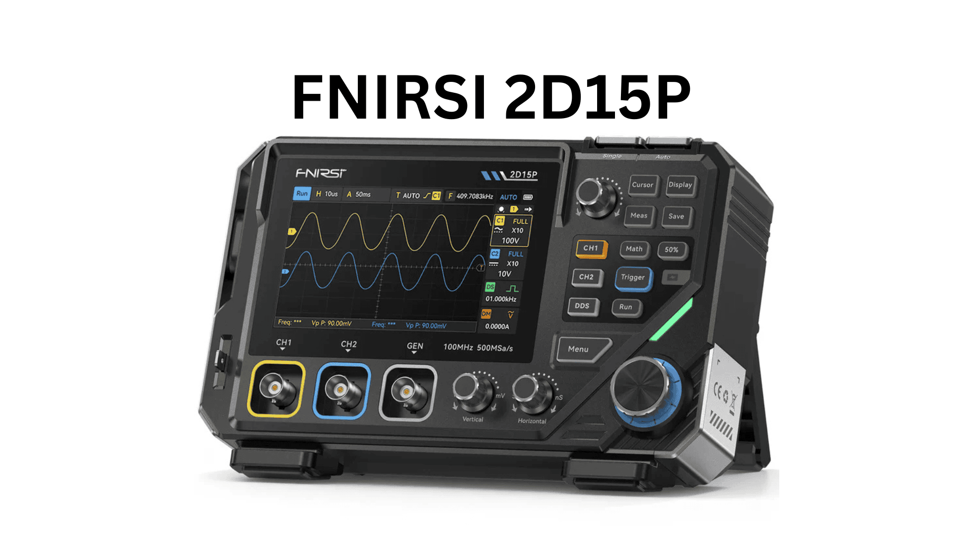
FNIRSI 2D15P User Manual
⚠️ SAFETY INFORMATION
Safety Terms and Symbols
WARNING: Indicates conditions or actions that could result in personal injury or loss of life.
CAUTION: Indicates conditions or actions that may damage the product or other property.
DANGER: Indicates that performing this operation may cause injury.
Safety Precautions
- Before Use
- Read all safety information and operating instructions
- Ensure proper grounding when measuring high voltages
- Use only specified probes and accessories
- During Operation
- Do not exceed maximum input voltage ratings
- Keep hands away from probe tips when measuring high voltages
- Ensure proper ventilation during operation
- Do not operate in wet or explosive environments
- Electrical Safety
- Maximum input voltage: Check specifications for each measurement mode
- Always use appropriate probe attenuation (1×, 10×, 100×)
- Never touch exposed circuit parts when power is applied
- Be aware of residual charges in capacitors
- Battery Safety
- Use only the provided charger (5V/2A recommended)
- Do not expose to extreme temperatures
- Built-in 5000mAh rechargeable lithium battery
- Can be used while charging via Type-C port
- Environmental Conditions
- Operating temperature: 0°C to 40°C
- Storage temperature: -20°C to 60°C
- Humidity: < 85% RH (non-condensing)
- Altitude: < 2000m
PRODUCT OVERVIEW
What’s in the Box
Standard Accessories:
- FNIRSI 2D15P main unit
- 2× Oscilloscope probes (100MHz, 1×/10×)
- 2× Multimeter test leads
- Type-C charging cable
- User manual
- Carrying pouch
- Calibration certificate
Order your 2D15P today – 2-day UK delivery, 60-day easy returns
Control Panel Reference
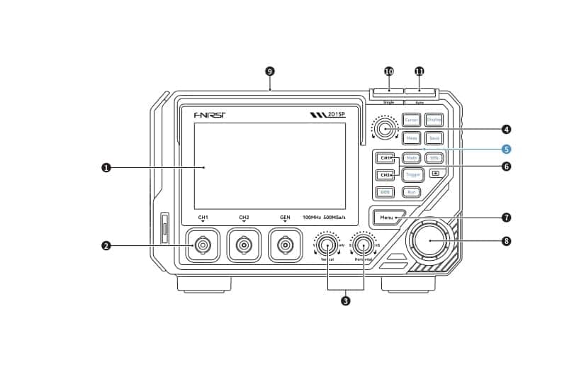
1. Display Area
Touchscreen operation supported
2. Signal Ports
• Channel signal input (CH1/CH2)
• Signal generator output (DDS)
3. Vertical/Horizontal Knobs
• Vertical: Adjusts waveform height and voltage range
• Horizontal: Adjusts waveform width and time base
4. Function Knob
• Cursor enabled: Rotate to move cursor left/right (press to switch up/down)
• Cursor disabled: Adjusts channel voltage offset
5. Function Buttons
• Cursor – Activate cursor for precise voltage/time measurements
• Display – Adjust brightness, color, persistence, grid type, display mode
• Measure – Select from 13 measurement types (frequency, amplitude, duty cycle, etc.)
• Save – Capture screenshot of current display
• Math – Enable waveform math functions (6 operation types)
• 50% – Quick-set trigger level and offsets to center position
• Trigger – Configure trigger channel, mode, and edge settings
• Run – Start/stop signal acquisition (green = running, red = stopped)
• DDS – Signal generator settings (sine, square, triangle waveforms)
6. CH1/CH2 Switch
Quick channel selection for fast waveform viewing
7. Menu Button
Open main menu for function selection and adjustments
8. Trigger Control Knob
Adjust trigger level and delay for stable waveform display
9. Multimeter Interface
• 10A terminal (high current)
• mA terminal (low current)
• COM terminal (common ground)
10. Single Trigger
Capture one specific trigger event
11. Auto Trigger
Automatic trigger adjustment for stable display
Key Features
3-in-1 Functionality:
- 100MHz Dual-Channel Oscilloscope with phosphor display
- True RMS Digital Multimeter (6000 counts)
- Portable Design – 30% lighter and more compact
Oscilloscope Specifications:
- Bandwidth: 100 MHz (dual channel)
- Sampling Rate: 1 GSa/s (real-time)
- Memory Depth: Configurable
- Channels: 2 independent analog channels
- Vertical Sensitivity: 5 mV/div to 10 V/div
- Time Base: 2 ns/div to 50 s/div
- Trigger Types: Edge, pulse, video, slope
- Display: Phosphor persistence mode for capturing rare events
Multimeter Specifications:
- DC Voltage: 600 mV to 1000V (±0.5% accuracy)
- AC Voltage: 600 mV to 1000V (±1.0% accuracy)
- DC Current: 60 mA to 10A (±1.0% accuracy)
- AC Current: 60 mA to 10A (±1.5% accuracy)
- Resistance: 600Ω to 60MΩ (±1.0% accuracy)
- Capacitance: 10 nF to 100 mF (±3.0% accuracy)
- Frequency: 10 Hz to 10 MHz
- Duty Cycle: 0.1% to 99.9%
- Diode Test: Yes
- Continuity Test: Yes with buzzer
- NCV (Non-Contact Voltage): Detection function
- True RMS: Yes
General Specifications:
- Display: 3.5″ IPS LCD with high resolution
- Battery: 5000mAh rechargeable lithium-ion
- Battery Life: Up to 6 hours continuous use
- Charging: Type-C, 5V/2A (can use while charging)
- Storage: Internal memory for waveforms and screenshots
- Connectivity: USB for data transfer
- Size: Compact handheld form factor (30% smaller than previous models)
- Weight: Approximately 400g
FUNCTION OVERVIEW
Device Layout
Front Panel Controls:
Oscilloscope Section:
- Channel 1 (CH1) input – BNC connector (yellow)
- Channel 2 (CH2) input – BNC connector (cyan)
- Signal generator output (if equipped)
- Display screen (3.5″ IPS)
- Control knobs and buttons
Multimeter Section:
- COM (common) terminal – Black
- VΩHz terminal – Red (voltage, resistance, frequency)
- mA terminal – Red (current measurement up to 600mA)
- 10A terminal – Red (high current measurement)
- Function rotary selector switch
- Range/mode buttons
Side/Top Controls:
- Power button
- Menu/function buttons
- Vertical position controls
- Horizontal timebase control
- Trigger controls
- USB/Type-C port
Operating Modes
Mode 1: Oscilloscope Operation
Basic Oscilloscope Functions:
- Channel Setup
- Turn CH1/CH2 on or off
- Set vertical sensitivity (V/div)
- Select coupling mode (DC, AC, GND)
- Choose probe attenuation (1×, 10×, 100×)
- Adjust vertical position
- Timebase Control
- Adjust horizontal time scale (s/div)
- Position trigger point horizontally
- Enter roll/scroll mode for slow signals
- Trigger Settings
- Select trigger source (CH1, CH2, EXT)
- Set trigger type (Edge, Pulse, Video, Slope)
- Adjust trigger level
- Choose trigger mode (Auto, Normal, Single)
- Set trigger edge (Rising, Falling, Both)
- Measurement Functions
- Automatic measurements (up to 24 parameters)
- Cursor measurements (time, voltage)
- Math functions (Add, Subtract, Multiply, FFT)
- Statistical analysis
- Display Modes
- Normal display
- Phosphor persistence – Shows signal history with intensity grading
- XY mode (Lissajous patterns)
- Roll mode for slow signals
- Advanced Features
- Waveform storage and recall
- Screenshot capture
- Pass/Fail testing
- Automatic setup (Auto button)
Phosphor Display Mode: The phosphor persistence feature displays waveform history with different intensity levels, similar to analog oscilloscopes. This is extremely useful for:
- Capturing intermittent glitches
- Analyzing signal jitter
- Viewing modulated signals
- Observing rare events
Mode 2: Multimeter Operation
Measurement Functions:
- Voltage Measurement (DC/AC)
- Rotate selector to V (DC) or V~ (AC)
- Connect red lead to VΩHz terminal
- Connect black lead to COM terminal
- Touch probes to measurement point
- Read display (True RMS for AC)
- Current Measurement (DC/AC)
- For 0-600mA: Connect red lead to mA terminal
- For 0-10A: Connect red lead to 10A terminal
- Rotate selector to A (DC) or A~ (AC)
- Connect meter in series with circuit
- Read display
- Resistance Measurement
- Rotate selector to Ω
- Connect leads to VΩHz and COM
- Touch probes to resistor
- Read resistance value
- Capacitance Measurement
- Rotate selector to capacitance symbol
- Discharge capacitor before measuring
- Connect leads to VΩHz and COM
- Touch probes to capacitor
- Wait for stable reading
- Diode Test
- Rotate selector to diode symbol
- Connect leads as for resistance
- Forward bias: displays voltage drop (typically 0.4-0.7V)
- Reverse bias: displays “OL” (open)
- Continuity Test
- Rotate selector to continuity symbol ()))
- Touch probes to circuit points
- Buzzer sounds if resistance < 50Ω
- Display shows resistance value
- Frequency Measurement
- Rotate selector to Hz
- Connect signal to VΩHz terminal
- Display shows frequency and duty cycle
- Non-Contact Voltage Detection (NCV)
- Special mode for detecting AC voltage without contact
- Hold device near AC power line
- LED and/or buzzer indicates voltage presence
- Useful for finding live wires in walls
Mode 3: Combined Operation
The 2D15P allows simultaneous oscilloscope and multimeter operation:
- View waveform on oscilloscope channels
- Simultaneously measure DC voltage, current, or resistance with DMM
- Ideal for power supply troubleshooting
- Correlate waveform behavior with DC parameters
COMMON MEASUREMENT TASKS
Oscilloscope Measurements
1. Basic Signal Viewing
Quick Start:
- Connect probe to CH1 input
- Connect probe ground clip to circuit ground
- Touch probe tip to signal point
- Press AUTO button for automatic setup
- Adjust vertical and horizontal scales as needed
Manual Adjustment:
- If signal too large/small: Adjust V/div knob
- If signal too fast/slow: Adjust s/div knob
- If waveform not stable: Adjust trigger level
2. Measuring Digital Logic Signals
Setup:
- Trigger mode: Normal (not Auto)
- Coupling: DC
- Probe: 10× position
- Timebase: Start with 1 μs/div
Procedure:
- Connect probe to logic signal
- Set trigger level between high and low states
- Choose rising or falling edge trigger
- Capture signal and analyze timing
3. Power Supply Ripple Measurement
Setup:
- Coupling: AC (blocks DC, shows only ripple)
- Probe: 10×
- Vertical sensitivity: Start with 10 mV/div
- Bandwidth limit: ON (reduces noise)
Procedure:
- Connect probe to power supply output
- Wait 2-3 seconds for DC offset to stabilize
- Press AUTO or manually adjust to see ripple
- Measure pk-pk voltage for ripple amplitude
4. Frequency and Period Measurement
Automatic:
- Press Measure menu
- Select Frequency and Period parameters
- Display shows measurements automatically
Manual with Cursors:
- Enable time cursors
- Position cursors at one complete cycle
- Read ΔT (time difference)
- Frequency = 1 / ΔT
5. Rise Time and Fall Time
Procedure:
- Display clear edge transition
- Enable time cursors
- Position cursors at 10% and 90% amplitude points
- Read rise time or fall time from ΔT
6. Pulse Width and Duty Cycle
Automatic:
- Select Pulse Width+ and Duty Cycle+ measurements
- For negative pulses, use Pulse Width- and Duty Cycle-
Manual:
- Use time cursors to measure high time (t_high) and period (T)
- Duty Cycle = (t_high / T) × 100%
Multimeter Measurements
1. Measuring Battery Voltage
Procedure:
- Rotate selector to V (DC voltage)
- Red lead to VΩHz, black to COM
- Touch red to battery +, black to battery –
- Read voltage on display
2. Testing LEDs and Diodes
Procedure:
- Rotate selector to diode test mode
- Disconnect component from circuit
- Touch red probe to anode, black to cathode
- Good diode: 0.4-0.7V (silicon), LED may light
- Reverse polarity: Should show “OL”
3. Checking Fuse Continuity
Procedure:
- Rotate selector to continuity mode ()))
- Touch probes to both ends of fuse
- Good fuse: Beep sound, ~0Ω displayed
- Blown fuse: No beep, “OL” displayed
4. Measuring AC Line Voltage
⚠️ WARNING: High voltage – be extremely careful!
Procedure:
- Rotate selector to V~ (AC voltage)
- Ensure leads in correct terminals
- Do not touch metal probe tips
- Insert probes into outlet (line and neutral)
- Read voltage (should be ~110V or ~220V depending on region)
5. Current Draw Testing
For currents < 600mA:
- Rotate selector to A or A~
- Red lead to mA terminal, black to COM
- Break circuit and insert meter in series
- Read current
For currents 600mA to 10A:
- Move red lead to 10A terminal
- Rotate selector appropriately
- Insert in series with load
- Do not exceed 10A
- Do not measure for more than 10 seconds at high current
6. Capacitor Testing
Procedure:
- Discharge capacitor completely first!
- Rotate selector to capacitance mode
- Remove capacitor from circuit
- Connect leads to capacitor terminals
- Wait for reading to stabilize (may take several seconds for large caps)
- Compare to rated value (±20% tolerance is normal)
❗ TROUBLESHOOTING
Oscilloscope Issues
| Problem | Possible Cause | Solution |
|---|---|---|
| No display / blank screen | Power off or battery dead | Charge device, press power button |
| No waveform, only flat line | Paused or incorrect settings | Press RUN button, press AUTO |
| Waveform unstable / rolling | Trigger not set properly | Adjust trigger level, change trigger mode |
| Signal too small | Vertical sensitivity too low | Decrease V/div setting |
| Signal clipped (top/bottom cut off) | Vertical sensitivity too high | Increase V/div setting |
| Signal too fast/slow | Timebase incorrect | Adjust s/div setting |
| Measurements show 0 | Signal not triggered or insufficient waveform | Ensure proper trigger, show full cycles on screen |
| Cannot capture glitch | Trigger mode wrong | Use Single trigger mode, adjust trigger |
| Display flickering | Interference or loose connection | Check probe connections, move away from interference |
Multimeter Issues
| Problem | Possible Cause | Solution |
|---|---|---|
| Display shows “OL” | Over-range or open circuit | Check connections, select higher range |
| Display shows “0” or very low | Short circuit or wrong mode | Check for shorts, verify function selector |
| No beep in continuity mode | Resistance > 50Ω or open | Check connections, component may be faulty |
| Erratic readings | Poor contact or interference | Clean probe tips, ensure good contact |
| Current measurement blows fuse | Measured in voltage mode or current too high | Replace fuse, use correct terminals |
| Battery not charging | Wrong charger or faulty port | Use 5V/2A Type-C charger, check port |
| Inaccurate readings | Needs calibration | Perform zero adjustment, contact service |
General Issues
| Problem | Possible Cause | Solution |
|---|---|---|
| Device won’t turn on | Battery fully discharged | Charge for 30 minutes, then try |
| Device turns off suddenly | Low battery or overheat | Charge device, allow to cool |
| Cannot save files | Memory full | Delete old files via menu |
| USB not recognized | Wrong cable or driver | Use provided cable, install drivers |
| Screen not responding | Software glitch | Restart device (hold power 10 seconds) |
MAINTENANCE
Regular Maintenance
Daily:
- Wipe screen and case with soft, dry cloth
- Check probe tips for damage or wear
- Ensure all terminals are clean
Weekly:
- Discharge and recharge battery fully (battery health)
- Check probe compensation (square wave test)
Monthly:
- Clean all connectors with contact cleaner
- Verify calibration with known sources
- Update firmware if available
Probe Maintenance
Probe Compensation:
- Connect probe to CAL output terminal
- Observe square wave on screen
- If top is rounded or peaked, adjust probe trimmer capacitor
- Adjust until square wave has flat top and sharp corners
Probe Care:
- Do not bend probe cables sharply
- Store with probe tips protected
- Replace damaged probe tips immediately
- Keep probes dry and clean
Battery Care
- Charge regularly – Don’t let battery fully discharge frequently
- Storage – If storing > 1 month, charge to 50-60%
- Temperature – Avoid charging in extreme temperatures
- Lifespan – Battery typically lasts 300-500 charge cycles
- Replacement – Contact service center for battery replacement
Calibration
For best accuracy, calibration should be performed:
- Every 12 months
- After repair
- If measurements seem inaccurate
- Contact authorized service center for professional calibration
Cleaning
Do:
- Use soft, lint-free cloth
- Use mild detergent solution for stubborn stains
- Dry thoroughly before use
Don’t:
- Use solvents, alcohol, or abrasive cleaners
- Spray liquids directly on device
- Submerge in water
- Use high-pressure air
CONTACT INFORMATION
Manufacturer: FNIRSI
Customer Support:
- Visit official website for latest drivers and firmware
- Email support for technical questions
- Online forum for user community
Service Centers:
- Check website for authorized service centers in your region
- Keep purchase receipt for warranty service
🛡️ WARRANTY INFORMATION
Standard Warranty
Duration: 12 months from date of purchase
Coverage: Manufacturing defects in materials and workmanship
What’s Covered:
- Defective components
- Manufacturing defects
- Normal operation failures
What’s NOT Covered:
- Damage from misuse or abuse
- Unauthorized modifications
- Damage from incorrect input voltages
- Normal wear and tear (e.g., probe tips)
- Cosmetic damage
- Battery degradation (normal aging)
- Liquid damage
- Dropped or impact damage
Warranty Claim Process
- Contact customer support
- Provide proof of purchase
- Describe problem in detail
- Follow return instructions if repair needed
- Authorized service center will evaluate
- Repair or replace under warranty terms
Extended Support
- Firmware updates: Free for life
- Technical support: Available online
- Replacement parts: Available for purchase
- User community: Active forum and resources
APPENDIX A: ACCESSORIES LIST
Standard Package Contents
✓ FNIRSI 2D15P main unit (1 pc) ✓ 100MHz oscilloscope probe with 1×/10× switch (2 pcs) ✓ Multimeter test leads – Red/Black pair (1 set) ✓ Type-C charging cable (1 pc) ✓ User manual (this document) ✓ Carrying pouch (1 pc) ✓ Quick start guide ✓ Calibration certificate
Optional Accessories (Sold Separately)
- High-voltage probe (100×, 1000×)
- Current probe / clamp meter
- Differential probe
- Logic analyzer probes
- Temperature probe (K-type thermocouple)
- Protective hard case
- Spare probes and test leads
- Automotive probe kit
SPECIFICATIONS SUMMARY
| Category | Specification |
|---|---|
| Oscilloscope | |
| Bandwidth | 100 MHz (dual channel) |
| Sampling Rate | 1 GSa/s |
| Channels | 2 analog channels |
| Vertical Resolution | 8-bit ADC |
| Vertical Sensitivity | 5 mV/div to 10 V/div |
| Vertical Accuracy | ±3% |
| Input Impedance | 1 MΩ // 15 pF |
| Max Input Voltage | 400 Vpk (DC + AC peak) |
| Time Base Range | 2 ns/div to 50 s/div |
| Trigger Types | Edge, Pulse, Video, Slope |
| Display Mode | Phosphor persistence |
| Multimeter | |
| Display Count | 6000 counts |
| DC Voltage | 600mV to 1000V (±0.5%) |
| AC Voltage (True RMS) | 600mV to 1000V (±1.0%) |
| DC Current | 60mA to 10A (±1.0%) |
| AC Current (True RMS) | 60mA to 10A (±1.5%) |
| Resistance | 600Ω to 60MΩ (±1.0%) |
| Capacitance | 10nF to 100mF (±3.0%) |
| Frequency | 10Hz to 10MHz |
| Duty Cycle | 0.1% to 99.9% |
| General | |
| Display | 3.5″ IPS color LCD |
| Battery | 5000mAh Li-ion |
| Battery Life | Up to 6 hours |
| Charging | Type-C, 5V/2A |
| Dimensions | Compact handheld (30% smaller) |
| Weight | ~400g |
| Operating Temp | 0°C to 40°C |
| Storage Temp | -20°C to 60°C |
IMPORTANT NOTES
- First Use: Fully charge the device before first use
- Probe Attenuation: Always match probe switch position (1×/10×) with oscilloscope setting
- High Voltage: Never exceed 400V on oscilloscope inputs or 1000V on multimeter
- Current Measurement: Use 10A terminal for currents > 600mA, limit measurement time
- Capacitor Testing: Always discharge capacitors before measuring
- Firmware Updates: Check website periodically for firmware updates
- Data Backup: Save important waveforms before they are overwritten
- Environmental: Do not use in wet, explosive, or extremely dusty environments
Document Version: English Edition v1.2
Based on: FNIRSI 2D15P Official Manual
This manual has been carefully adapted for English-speaking users with improved clarity and organization while maintaining all original technical information and safety warnings.
Need Help?
- Quick Start: Press AUTO button for automatic waveform setup
- Online Support: Visit FNIRSI official website
- Video Tutorials: Check YouTube for 2D15P tutorials
- User Community: Join online forums for tips and tricks
Thank you for choosing FNIRSI 2D15P!