FNIRSI user manual

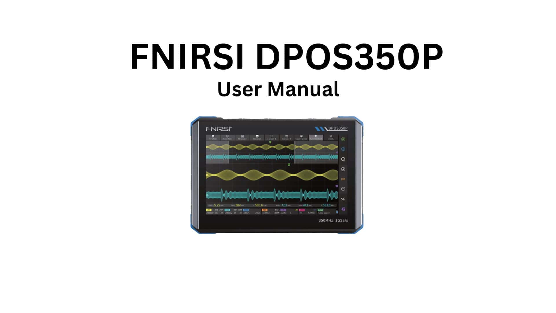
Fnirsi DPOS350P English Manual

1. Product Introduction

The FNIRSI DPOS350P is an advanced 4-in-1 multi-function tablet oscilloscope that combines four essential testing instruments in one portable device:

Key Features

  • Digital Oscilloscope: 100 MHz bandwidth, 1 GSa/s, dual-channel
  • Signal Generator: 0.1 Hz – 20 MHz, multiple waveforms
  • Digital Multimeter: True RMS, voltage/current/resistance
  • Logic Analyzer: 8 channels with protocol decoding
  • Display: 7-inch touchscreen (1024×600)
  • Battery: Built-in rechargeable lithium battery
  • Storage: Save waveforms and screenshots
  • Protocols: I2C, SPI, UART, CAN, LIN, 1-Wire decoding

Applications

  • Electronics design and debugging
  • Circuit testing and analysis
  • Education and training
  • Field service and repair
  • Embedded system development
  • Automotive diagnostics

2. Special Precautions

Electrical Safety

  • ⚠ Maximum input voltage: 400V DC or 400V AC (peak)
  • ⚠ Do not exceed rated input ranges
  • ⚠ Use only specified probes and accessories
  • ⚠ Ensure proper grounding when testing AC circuits
  • ⚠ Do not measure high-voltage circuits without proper protection
  • ⚠ Discharge capacitors before testing

Operating Precautions

  • Operating temperature: 0°C to 40°C
  • Storage temperature: -20°C to 60°C
  • Humidity: ≤80% RH (non-condensing)
  • Do not operate in wet or humid environments
  • Keep away from strong magnetic fields
  • Avoid dropping or impact damage
  • Do not disassemble the unit

Maintenance

  • Clean with soft, dry cloth only
  • Do not use chemical solvents
  • Calibrate regularly for accuracy
  • Store in cool, dry place
  • Charge battery at least once every 3 months during storage

3. Product Parameters

page 09

Order your DPOS350P today – 2-day UK delivery, 60-day easy returns
Check the review for DPOS350

Oscilloscope Specifications

Bandwidth100 MHz
Channels2 (CH1, CH2)
Sample Rate1 GSa/s (single channel), 500 MSa/s (dual channel)
Memory Depth50K points per channel
Vertical Sensitivity5 mV/div – 10 V/div (1-2-5 steps)
Input Impedance1 MΩ ± 2% // 15 pF ± 5 pF
Input CouplingDC, AC, GND
Maximum Input Voltage400V (DC + AC peak)
Vertical Resolution8 bits
Timebase Range5 ns/div – 500 s/div
Trigger ModesAuto, Normal, Single
Trigger TypesEdge, Pulse, Video, Slope

Signal Generator Specifications

Frequency Range0.1 Hz – 20 MHz
WaveformsSine, Square, Triangle, Sawtooth
Amplitude Range0 – 3.3V (peak-to-peak)
Output Impedance50 Ω
Frequency Accuracy±0.01%
Duty Cycle (Square)10% – 90%

Multimeter Specifications

FunctionRangeAccuracy
DC Voltage0 – 600V±(0.5% + 5 digits)
AC Voltage (True RMS)0 – 600V±(1.0% + 10 digits)
DC Current0 – 10A±(1.0% + 5 digits)
AC Current (True RMS)0 – 10A±(1.5% + 10 digits)
Resistance0 – 60 MΩ±(1.0% + 5 digits)
Capacitance0 – 10 mF±(3.0% + 10 digits)
Frequency10 Hz – 10 MHz±(0.1% + 3 digits)
Duty Cycle1% – 99%±(1% + 2 digits)
Diode Test0 – 3V±(2% + 5 digits)
Continuity Test< 50 ΩBuzzer alert
Temperature (K-type)-20°C – 400°C±(1.0% + 3°C)

Logic Analyzer Specifications

Channels8 digital channels (D0-D7)
Sample Rate100 MSa/s
Memory Depth10K samples per channel
Input Voltage Range-10V to +10V
Logic ThresholdTTL, CMOS (adjustable)
Protocol DecodingI2C, SPI, UART, CAN, LIN, 1-Wire

General Specifications

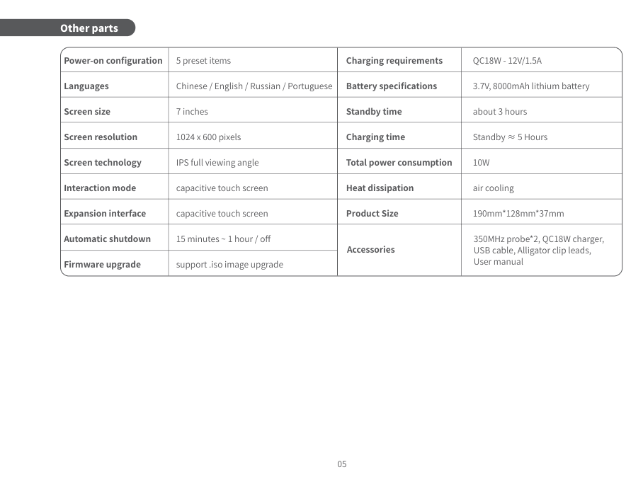
Display7-inch TFT LCD, 1024×600 resolution
TouchscreenCapacitive multi-touch
Battery4000 mAh lithium-ion
Battery Life4-6 hours (typical use)
Charging Time3-4 hours (5V/2A adapter)
USB InterfaceType-C (charging + data transfer)
Storage8 GB internal memory
File FormatsBMP (screenshots), CSV (data export)
Operating Temperature0°C to 40°C
Storage Temperature-20°C to 60°C
Dimensions200 mm × 130 mm × 30 mm
WeightApprox. 450g


4. Function Description

page 10

Front Panel Components

  1. 7-inch touchscreen display
  2. Power button (press 3 seconds to power on/off)
  3. BNC connectors for CH1 and CH2 (oscilloscope inputs)
  4. Signal generator output (BNC connector)
  5. Logic analyzer input connector (8-pin)
  6. Multimeter input jacks (COM, V/Ω, mA, 10A)
  7. Type-C USB port (charging and data)
  8. Reset button (firmware recovery)

Touchscreen Interface

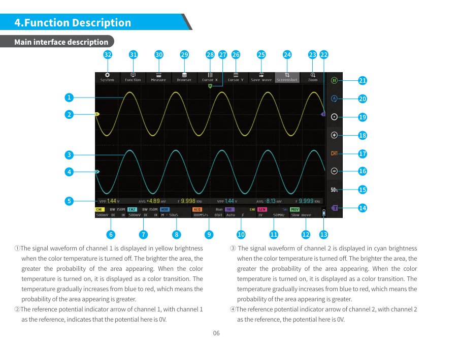
  • Mode Selection Icons: Switch between OSC/DMM/SIG/LA modes
  • Settings Menu: Access system settings and calibration
  • File Manager: Browse and manage saved files
  • Screenshot Button: Capture current screen (BMP format)
  • Help Button: Quick reference guide

Oscilloscope Mode

  • Vertical Controls: Adjust voltage scale (V/div)
  • Horizontal Controls: Adjust time scale (s/div)
  • Trigger Settings: Configure trigger type and level
  • Run/Stop Button: Start/pause waveform acquisition
  • Auto Setup: Automatic configuration for input signal
  • Measurement Menu: Select automatic measurements
  • Cursor Mode: Manual measurements with cursors
  • Math Functions: Add, subtract, multiply, divide, FFT

Signal Generator Mode

  • Waveform Selection: Sine, square, triangle, sawtooth
  • Frequency Adjustment: 0.1 Hz – 20 MHz
  • Amplitude Control: 0 – 3.3V peak-to-peak
  • Duty Cycle (Square): 10% – 90% adjustable
  • Output Enable/Disable: Toggle signal output on/off

Multimeter Mode

  • Function Selection: DC/AC voltage, current, resistance
  • Range Selection: Auto or manual range selection
  • Hold Function: Freeze current reading
  • Relative Mode: Zero/offset adjustment
  • Min/Max/Avg Recording: Track measurement statistics

Logic Analyzer Mode

  • Channel Enable: Select active channels (D0-D7)
  • Threshold Settings: Set logic level threshold
  • Trigger Configuration: Pattern trigger setup
  • Protocol Decoder: Select I2C/SPI/UART/CAN/LIN/1-Wire
  • Data Export: Save decoded data to CSV file

5. Operation Guide

Basic Setup

Step 1: Initial Power-On

  • Charge the device fully before first use (3-4 hours)
  • Press and hold power button for 3 seconds
  • System will boot and display main menu (10-15 seconds)
  • Select your preferred mode from the home screen

Step 2: Oscilloscope Basic Operation

  1. Connect oscilloscope probe to CH1 or CH2 BNC connector
  2. Connect probe to circuit under test
  3. Touch ‘OSC’ icon to enter oscilloscope mode
  4. Press ‘Auto’ button for automatic setup
  5. Adjust V/div and s/div for optimal viewing
  6. Configure trigger settings if needed
  7. Press ‘Run’ to start continuous acquisition

Step 3: Signal Generator Operation

  1. Connect BNC cable from SIG output to your circuit
  2. Touch ‘SIG’ icon to enter signal generator mode
  3. Select waveform type (sine/square/triangle/sawtooth)
  4. Set frequency using on-screen controls or keypad
  5. Adjust amplitude (0-3.3V peak-to-peak)
  6. For square wave: adjust duty cycle (10%-90%)
  7. Touch ‘Output ON’ to enable signal generation

Step 4: Multimeter Operation

  1. Connect test leads to appropriate jacks:
    • Red lead to V/Ω jack (voltage/resistance)
    • Black lead to COM jack (common)
    • For current: red lead to mA or 10A jack
  2. Touch ‘DMM’ icon to enter multimeter mode
  3. Select measurement function (V, A, Ω, etc.)
  4. Select AC or DC as appropriate
  5. Choose auto or manual range
  6. Connect probes to circuit
  7. Read measurement on display

Step 5: Logic Analyzer Operation

  1. Connect logic analyzer probe cable to 8-pin connector
  2. Connect probe clips to digital signals (D0-D7)
  3. Touch ‘LA’ icon to enter logic analyzer mode
  4. Enable channels you want to monitor
  5. Set logic threshold (TTL/CMOS)
  6. Configure trigger conditions
  7. Select protocol decoder if analyzing I2C/SPI/UART/etc.
  8. Press ‘Run’ to start capture

Advanced Operations

Protocol Decoding Setup

  • I2C Decoding: Assign SDA and SCL signals to channels. Decoded data shows: Address, R/W, Data, ACK/NACK
  • SPI Decoding: Assign MOSI, MISO, CLK, CS signals. Configure clock polarity and phase
  • UART Decoding: Assign TX and RX signals. Set baud rate, data bits, parity, stop bits

FFT Analysis (Oscilloscope)

  1. Capture time-domain waveform
  2. Touch ‘Math’ menu
  3. Select ‘FFT’ function
  4. Frequency spectrum appears on display
  5. Adjust FFT window type (Hanning, Hamming, Blackman)

Saving and Exporting Data

  • Screenshots: Touch camera icon (saves as BMP)
  • Waveform Data: Menu → Save → CSV format
  • File Access: Connect USB cable and transfer to PC

6. Common Issues and Diagnostics

IssuePossible CauseSolution
Device won’t power onBattery depletedCharge for 30 min
System frozenPress reset button
No waveform displayWrong V/div scalePress ‘Auto’ button
No triggerAdjust trigger level
Probe damagedTest probe continuity
Signal generator no outputOutput disabledEnable output button
Amplitude = 0VIncrease amplitude
Cable issueCheck BNC connection
Multimeter reading ‘OL’Range too lowSwitch to higher range
Open circuitCheck connections
Logic analyzer no dataThreshold wrongAdjust threshold level
Probe not connectedCheck all connections
Sample rate lowIncrease sample rate
Touchscreen unresponsiveScreen protectorRemove if too thick
Needs calibrationSettings → Calibrate
Battery drains quicklyBrightness highReduce screen brightness
Old batteryContact support
Inaccurate measurementsNeeds calibrationPerform calibration
Temperature driftAllow warm-up time

Calibration Procedure

  1. Let device warm up for 30 minutes
  2. Go to Settings → Calibration
  3. Follow on-screen instructions
  4. Use provided calibration signals
  5. Complete all calibration steps

Firmware Update

  1. Download latest firmware from www.fnirsi.com
  2. Copy .bin file to device via USB
  3. Settings → System → Firmware Update
  4. Select firmware file and confirm
  5. Wait for update to complete (5-10 minutes)
  6. Device will restart automatically

7. Contact Us

Manufacturer

CompanyShenzhen Zhuo Yue Xin Technology Co., Ltd.
BrandFNIRSI
ProductDPOS350P 4-in-1 Tablet Oscilloscope
ModelDPOS350P
VersionV1.6

Support

Websitewww.fnirsi.com
Emailsupport@fnirsi.com
DownloadsManuals, firmware, software at www.fnirsi.com/support
Video GuidesAvailable on YouTube and website

8. Warranty Instructions

Warranty Coverage

  • Period: 12 months from date of purchase
  • Covers: Manufacturing defects, component failures
  • Includes: Free repair or replacement (at manufacturer’s discretion)

Warranty Exclusions

  • ✗ Damage from misuse, abuse, or accidents
  • ✗ Unauthorized modifications or repairs
  • ✗ Normal wear and tear (battery, screen protector)
  • ✗ Damage from improper storage or transportation
  • ✗ Cosmetic damage that doesn’t affect functionality

Warranty Claim Procedure

  1. Contact support@fnirsi.com with:
    • Proof of purchase (receipt or invoice)
    • Serial number (on back label)
    • Description of issue with photos/videos
  2. Await response with instructions (1-2 business days)
  3. Ship device to service center if required
  4. Repair/replacement completed within 15 business days
  5. Device returned via courier

Important Notes

  • Keep proof of purchase for warranty service
  • Register product at www.fnirsi.com for extended support
  • Warranty valid worldwide
  • Customer responsible for shipping costs to service center
  • Return shipping covered by FNIRSI

Check FNIRSI Manuals Hub

Check the manual for 1014D

Check the manual for 1013D

Check the manual for 2D15P

Check the manual for 2C53T

Check the manual for LCR-P1

Check the manual for DPS 150

Check the manual for DST 210

Similar Posts

  • FNIRSI-1014D Oscilloscope User Manual

    2-in-1 Digital Oscilloscope with Signal Generator Product Overview The FNIRSI-1014D is a versatile 2-in-1 device combining a dual-channel digital oscilloscope with a built-in signal generator. This cost-effective desktop instrument is designed for both maintenance professionals and R&D engineers, offering comprehensive features and high practicality. Key Specifications Major Features Oscilloscope Functions: Signal Generator Features: Data Management:…

  • FNIRSI LCR-P1 User Manual

    NOTICE TO USERS 1. PRODUCT INTRODUCTION The FNIRSI LCR-P1 Transistor Tester is a high-precision, multifunctional electronic testing device designed specifically for electronic engineers, technicians, and electronics enthusiasts. This device is intended for detecting and analyzing the performance and characteristics of semiconductor components such as: Key Features: Advanced Testing Capabilities: Component Detection: 2. PANEL INTRODUCTION Order your LCR-P1…

  • FNIRSI DPS-150 English User Manual

    ⚠️ User Notice Important Safety Information Product Introduction FNIRSI DPS-150 is a high-precision portable CNC DC power supply with advanced digital control capabilities. It features adjustable voltage and current output, multiple protection mechanisms, PC software control, and a compact portable design ideal for electronics development, testing, and maintenance work. Key Features Panel Introduction Front Panel Components…

  • FNIRSI DST-210 User Manual

    Multifunctional Oscilloscope Multimeter Version 1.2 Table of Contents 1. Safety Requirements 1.1 Environmental Requirements Precautions: Keep Away From: Disposal: Do not dispose of old batteries or equipment with household waste. Dispose according to national or local regulations. 2. Product Overview The DST-210 is a comprehensive multifunctional device launched by FNIRSI, integrating oscilloscope and multimeter capabilities…

  • FNIRSI 2C53T User Manual

    50MHz Dual Channel Oscilloscope Multimeter NOTICE TO USERS 1. PRODUCT INTRODUCTION The FNIRSI-2C53T is a comprehensive, highly practical 3-in-1 dual-channel digital oscilloscope designed for maintenance and R&D professionals. This device combines three major functions: Oscilloscope, Multimeter, and Signal Generator. Key Features: Oscilloscope Specifications: Multimeter Specifications: Signal Generator: Display & Power: 2. PANEL INTRODUCTION Order your 2C53T today – 2-day UK…

  • FNIRSI 2D15P User Manual

    ⚠️ SAFETY INFORMATION Safety Terms and Symbols WARNING: Indicates conditions or actions that could result in personal injury or loss of life. CAUTION: Indicates conditions or actions that may damage the product or other property. DANGER: Indicates that performing this operation may cause injury. Safety Precautions PRODUCT OVERVIEW What’s in the Box Standard Accessories: Order…