FNIRSI 2C53T User Manual
50MHz Dual Channel Oscilloscope Multimeter
NOTICE TO USERS
- This manual provides detailed instructions on how to use the product and important precautions. Please read this manual carefully and follow the instructions to ensure optimal performance.
- Do not use the instrument in flammable or explosive environments.
- Waste batteries and scrapped instruments must not be disposed of with household waste. Please follow national or local regulations for proper disposal.
- If you encounter any quality issues with the instrument or have questions about its use, please contact us immediately. We will resolve your concerns as quickly as possible.
1. PRODUCT INTRODUCTION
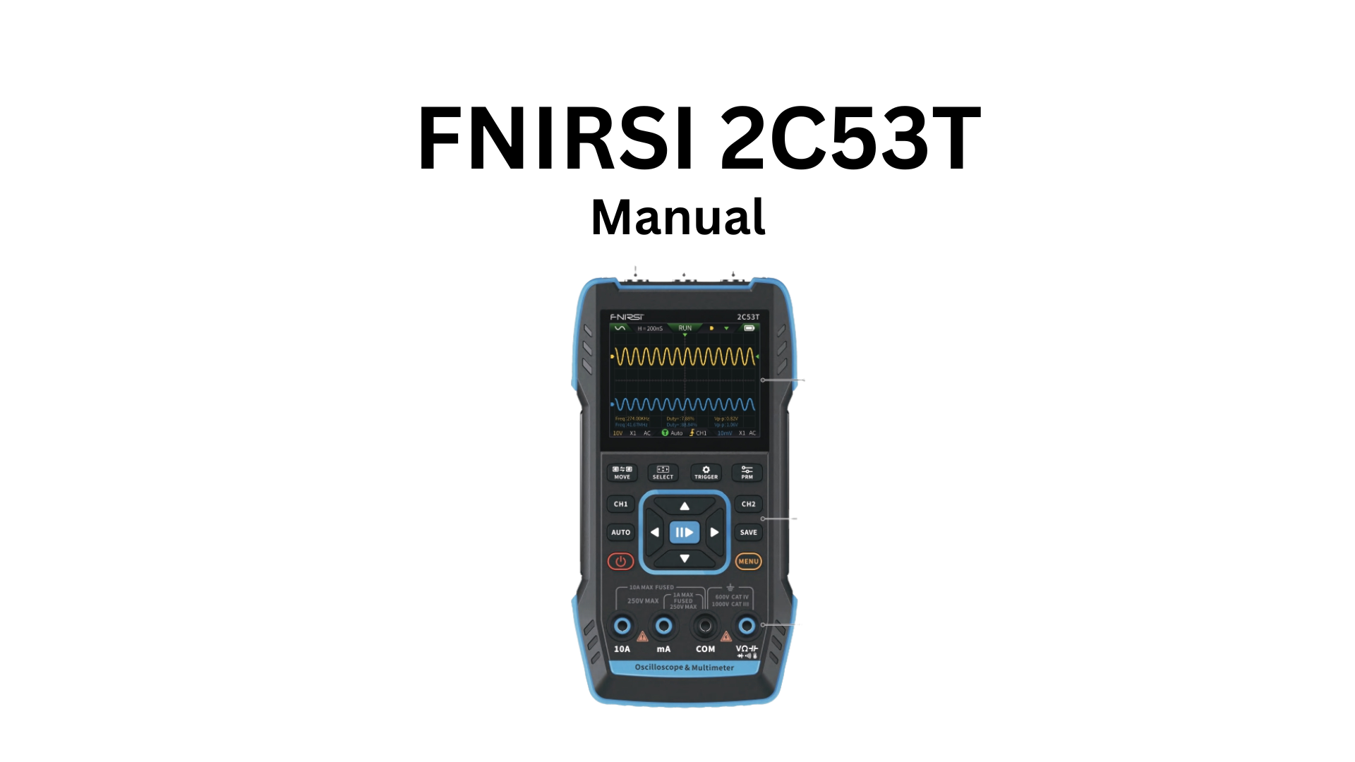
The FNIRSI-2C53T is a comprehensive, highly practical 3-in-1 dual-channel digital oscilloscope designed for maintenance and R&D professionals. This device combines three major functions: Oscilloscope, Multimeter, and Signal Generator.
Key Features:
Oscilloscope Specifications:
- FPGA + MCU + ADC hardware architecture
- 250MS/s sampling rate
- 50MHz analog bandwidth
- Built-in high-voltage protection module supporting up to ±400V peak voltage measurement
- Waveform screenshot save and review function for secondary analysis
Multimeter Specifications:
- 4½-digit, 20,000-count True RMS measurement
- DC/AC voltage and current measurement
- Capacitance, resistance, diode, and continuity testing
- Ideal for professionals, factories, schools, hobbyists, and home use
Signal Generator:
- Built-in DDS function signal generator
- Outputs 13 types of function signals
- Maximum output frequency: 50kHz (1Hz step resolution)
- Adjustable output frequency, amplitude, and duty cycle
Display & Power:
- 2.8-inch 320×240 high-resolution color LCD screen
- Built-in 3000mAh rechargeable lithium battery
- Up to 6 hours standby time
- Compact size with excellent portability
2. PANEL INTRODUCTION
Order your 2C53T today – 2-day UK delivery, 60-day easy returns
Check the review for 2C53T
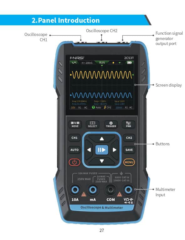
Front Panel Components:
- Oscilloscope Channel 1 Input Port
- Oscilloscope Channel 2 Input Port
- Function Signal Generator Output Port
- Screen Display Area
- Button Control Area
- Multimeter Interface
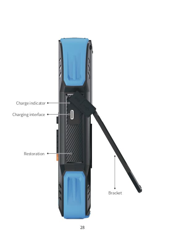
Rear Panel Components:
- Charging Indicator LED
- Charging Port (Type-C)
- Reset Button
- Device Stand
3. DEVICE PARAMETERS
| Specification | Value |
|---|---|
| Screen | 2.8-inch true color display |
| Resolution | 320×240 pixels |
| Charging | Type-C (5V/1A) |
| Battery | 3000mAh lithium battery |
| Supported Functions | Oscilloscope, Signal Generator, Digital Multimeter (see detailed parameters below) |
| Standby Time | 6 hours (theoretical maximum under lab conditions) |
| Product Dimensions | 167×89×35mm |
| Weight | 300g |
4. BUTTONS & FUNCTIONS
4.1 Oscilloscope – Button Operations
| Button | Press Type | Function |
|---|---|---|
| Power | Short press | Power ON/OFF |
| MENU | Short press | Return to previous screen |
| MENU | Long press | Return to Home page (function selection) |
| CH1 | Short press | CH1 settings |
| CH2 | Short press | CH2 settings |
| AUTO | Short press | Auto-adjust |
| AUTO | Long press | Baseline calibration※ |
| RUN/STOP | Short press | Start/Stop acquisition |
| RUN/STOP | Long press | 50% center adjustment |
| SAVE | Short press | Save screenshot |
| SAVE | Long press | Enter 9-grid view |
| ↕/↔ MOVE | Short press | Switch between CH1/CH2 adjustment |
| ↕/↔ MOVE | Long press | Quick access to Multimeter |
| ← → SELECT | Short press | Select directional key movement function |
| ← → SELECT | Long press | Quick access to Oscilloscope |
| TRIG | Short press | Trigger settings |
| TRIG | Long press | Quick access to Signal Generator |
| MENU | Short press | Parameter selection |
| MENU | Long press | Show/Hide measurement parameters |
※ Note: Baseline calibration takes time. Please be patient and do not operate the device during calibration. If accidentally interrupted, restart the calibration. Remove probes before calibrating.
4.2 Oscilloscope – Interface Description
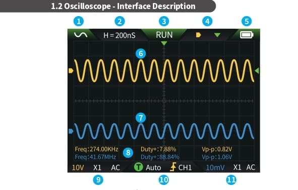
Interface Elements:
① Function Signal Generator Status Icons (13 waveform types):
- Sine wave, Square wave, Sawtooth wave, Half-wave, Full-wave
- Positive staircase, Negative staircase, Exponential rise, Exponential fall
- DC, Multi-tone, Sinc pulse, Lorentz wave
- Gray icon = output disabled
② Time Base: Horizontal time base indicating time length per major division
③ RUN/STOP Indicator:
- RUN = Running
- STOP = Paused
④ Control Mode Indicators:
- ⊕ = Left/Right keys control time base; Up/Down keys control vertical sensitivity (Yellow=CH1, Blue=CH2)
- ↕ = Left/Right keys control horizontal trigger position; Up/Down keys move waveform vertically
- T = Left/Right keys control horizontal trigger position; Up/Down keys control trigger level
- ┼ = Cursor enabled: Up/Down keys move cursor vertically; Left/Right keys move cursor horizontally
⑤ Battery Indicator:
- Full charge ⚡ / Low battery ⚠
- Low battery warning with countdown to auto shutdown
⑥ Channel 1 Waveform (Yellow)
⑦ Channel 2 Waveform (Blue)
⑧ Measurement Parameters Display
⑨ CH1 Settings Display: Vertical sensitivity, probe ratio, coupling mode
⑩ Trigger Information: Trigger mode, trigger edge, trigger channel
⑪ CH2 Settings Display: Vertical sensitivity, probe ratio, coupling mode
4.3 Oscilloscope – Waveform Screenshot Save
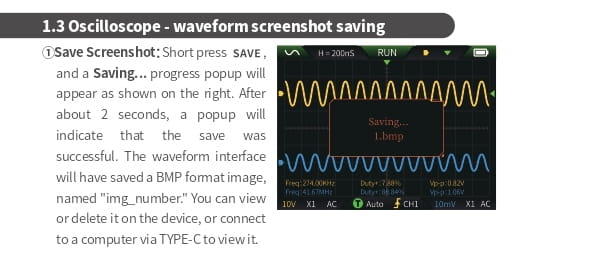
Saving Screenshots:
- Short press SAVE button
- “Saving…” prompt appears (~2 seconds)
- “Save successful” confirmation appears
- Waveform saved as BMP image file
- Files named as “img_001”, “img_002”, etc. (sequential numbering)
- View on device or connect to PC via Type-C
- Viewing Screenshots:
- Long press SAVE to enter screenshot gallery
- Press BACK to access saved waveform interface
- Use directional keys to select waveforms
- Use corresponding buttons for multi-select operations
- Check/uncheck with button press
⚠ Important: Storage is limited. Manual deletion required when full.
4.4 Oscilloscope – Parameters
| Parameter | Specification |
|---|---|
| Channels | Dual channel |
| Sampling Rate | 250MS/s |
| Analog Bandwidth | 50MHz (each channel independent) |
| Memory Depth | 1Kpts |
| Input Impedance | 1MΩ |
| Time Base Range | 10ns ~ 20s |
| Vertical Sensitivity | 10mV/div ~ 10V/div (X1 mode) |
| Maximum Voltage | ±400V |
| Trigger Modes | Auto, Normal, Single |
| Trigger Types | Rising edge, Falling edge |
| Display Modes | Y-T / Roll / X-Y |
| Coupling | AC / DC |
| Persistence | OFF, 500ms, 1s, ∞ |
| Math Operations | 8 basic operations + FFT |
| Waveform Screenshot | Supported |
| Export Waveform | Supported |
| Cursor Measurement | Supported |
5. SIGNAL GENERATOR
5.1 Signal Generator – Button Operations
| Button | Press Type | Function |
|---|---|---|
| Power | Short press | Power ON/OFF |
| Back | Short press | Return |
| Back | Long press | Return to Home page |
| OK | Short press | Confirm |
| RUN/STOP | Long press | Start/Stop output |
| ↕/↔ | Long press | Quick access to Multimeter |
| ← → | Long press | Quick access to Oscilloscope |
| TRIG | Long press | Quick access to Signal Generator |
5.2 Signal Generator – Interface Description
Interface Elements:
① Output Status Indicator: 13 waveform types (see detailed description on page 11)
② Battery Indicator: Full/Low battery status with auto-shutdown countdown
③ Output Waveform Selection (13 types): Sine, Square, Sawtooth, Half-wave, Full-wave, Positive staircase, Negative staircase, Exponential rise, Exponential fall, DC, Multi-tone, Sinc pulse, Lorentz wave
④ Waveform Preview: Gray = output disabled
⑤ Waveform Adjustment Parameters
Operation: Use Up/Down directional keys to select output waveform, then press Right key to enter parameter settings (adjust using directional keys)
5.3 Signal Generator – Parameters
| Parameter | Specification |
|---|---|
| Channels | Single channel |
| Frequency Range | 1Hz ~ 50kHz |
| Amplitude Range | 0.1V ~ 3.0V |
6. DIGITAL MULTIMETER
6.1 Multimeter – Button Operations
| Button | Press Type | Function |
|---|---|---|
| Power | Short press | Power ON/OFF |
| Back | Long press | Return to Home page |
| AUTO | Short press | Auto measurement |
| HOLD | Short press | Data hold |
| AC/DC | Short press | Switch AC/DC, Diode/Continuity modes |
| ← | Short press | Shift range left (according to UI) |
| → | Short press | Shift range right (according to UI) |
6.2 Multimeter – Interface Description
Interface Elements:
① REL: Relative measurement mode
② Current Measurement Range
③ Battery Indicator
④ Range Scale Bar
⑤ HOLD: Data hold status
⑥ Measured Value (main display)
⑦ Range Status Indicators:
- Yellow = selected range
- Gray = unselected range
⑧ Max/Min Average: Average of maximum and minimum values in current range
6.3 Multimeter – Test Lead Connections
Connection Instructions:
High Current Measurement:
- Red lead → 10A port
- Black lead → COM port
⚠ WARNING: Current exceeding 10A will blow the fuse. Estimate current before measurement.
Low Current Measurement:
- Red lead → mA port
- Black lead → COM port
⚠ WARNING: Current exceeding 1A will blow the fuse. Estimate current before measurement. If uncertain, use high current range first.
Auto/Voltage/Resistance/Capacitance/Temperature/Diode/Continuity Measurement:
- Red lead → VΩ port
- Black lead → COM port
- Switch to appropriate function range as needed
Note: Auto mode can only automatically identify voltage and resistance ranges. When measuring voltage, it automatically detects AC/DC voltage.
6.4 Multimeter – Parameters
| Function | Range | Accuracy |
|---|---|---|
| DC Voltage | 1.9999V / 19.999V / 199.99V / 1000V | ±(0.5%+3) |
| AC Voltage | 1.9999V / 19.999V / 199.99V / 750.0V | ±(1%+3) |
| DC Current | 19.999mA / 199.99mA / 1.9999A / 9.999A | ±(1.2%+3) |
| AC Current | 19.999mA / 199.99mA / 1.9999A / 9.999A | ±(1.5%+3) |
| Resistance | 199.99Ω / 1.9999KΩ / 19.999KΩ / 199.99KΩ / 1.9999MΩ / 19.999MΩ | ±(0.5%+3) to ±(2.0%+3) |
| Capacitance | 9.999nF / 99.99nF / 999.9nF / 9.999uF / 99.99uF / 999.9uF / 9.999mF / 99.99mF | ±(2.0%+5) to ±(5.0%+20) |
| Temperature | -55~1300℃ / -67~2372℉ | ±(2.5%+5) |
| Diode Test | Supported | – |
| Continuity Test | Supported | – |
7. SETTINGS
Settings Menu Options:
① Settings Selection:
- Language
- Sound & Light Settings
- Startup Function
- Auto Power Off
- USB Sharing
- About
- Factory Reset
② Detailed Settings:
Language: Chinese, English
Sound & Light Settings:
- Brightness: 25~100
- Sound: 0~10
Startup Function: OFF, Oscilloscope, Signal Generator, Multimeter (Sets which function launches at startup)
Auto Power Off: OFF, 15 minutes, 30 minutes, 1 hour
USB Sharing: Enable USB connection to PC for file transfer
About: Brand information, version number
Factory Reset: Restore default settings
Operation: Use Up/Down directional keys to select setting item, then press Right key to enter parameter adjustment (complete settings using directional keys)
8. FIRMWARE UPGRADE
Upgrade Procedure:
- Download the latest firmware from the official website and extract to desktop
- Connect device to PC using USB-A to Type-C cable
- Press and hold BACK button
- Then press POWER button to enter firmware upgrade mode
- PC will recognize device as USB drive
- Copy firmware file to the USB drive
- Device will automatically start upgrade after successful copy
- Monitor upgrade progress percentage
- Device will restart automatically when complete
- If upgrade fails, contact official customer service immediately
9. CUSTOMIZING STARTUP SCREEN
Custom Logo Procedure:
- Prepare replacement startup screen image
- Rename file to “LOGO2C53T.jpg”
- Power on device and connect to PC using USB-A to Type-C cable
- Enter Settings and enable USB Sharing
- Drag prepared logo file into device’s “LOGO” folder
- Custom logo will display at next startup
⚠ Important: Carefully verify filename, pixel dimensions, and format before changing logo.
10. COMMON CIRCUIT TESTING METHODS
1. Battery or DC Voltage Measurement
Range Selection:
- Battery voltage typically below 80V → Use 1X range
- Other DC voltages (uncertain) → Adjust based on actual situation
- Below 80V → 1X range
- Above 80V → 10X range
- Both probe and oscilloscope must be set to same range
Procedure:
① Set oscilloscope to Auto trigger mode (default at startup)
- Auto trigger mode is for periodic signals (DC voltage is a periodic signal)
② Set oscilloscope to appropriate range (default is 1X at startup)
③ Set to DC coupling mode
④ Insert probe and switch probe handle to corresponding range
⑤ Ensure battery is charged or DC voltage has output
⑥ Connect probe clip to battery/DC negative terminal, probe tip to positive terminal
⑦ Press AUTO button once – DC signal will display as a horizontal line
- Note: DC voltage has no waveform curve, only a vertical-shifting straight line
- VPP (peak-to-peak) and Frequency (F) will both be 0
2. Crystal Oscillator Measurement
Range Selection:
- Crystal oscillators easily stop oscillating when encountering capacitance
- 1X probe input capacitance: 100~300pF (high – causes oscillation stop)
- 10X range: 10~30pF (low – prevents oscillation stop)
- Use 10X range for both probe and oscilloscope
Procedure:
① Set to Auto trigger mode (default at startup)
- For periodic signals (crystal resonance sine wave is periodic)
② Set oscilloscope to 10X range (default is 1X at startup)
③ Set to AC coupling mode
④ Insert probe and switch probe handle to 10X range
⑤ Ensure crystal board is powered and running
⑥ Connect probe clip to crystal board ground (negative supply), pull out probe cap to expose needle tip, touch needle to one crystal pin
⑦ Press AUTO button once – crystal waveform will display
- If waveform is too small or large after AUTO, manually adjust in zoom mode
3. MOSFET or IGBT PWM Signal Measurement
Range Selection:
- Direct drive MOSFET/IGBT PWM signals typically 10V~20V
- PWM control signals typically 3~20V
- 1X range maximum: 80V (sufficient for PWM signals)
- Use 1X range for both probe and oscilloscope
Procedure:
① Set to Auto trigger mode (PWM is a periodic signal)
② Set to 1X range (default at startup)
③ Set to DC coupling mode
④ Insert probe and switch to 1X range
⑤ Ensure PWM board is outputting PWM signal
⑥ Connect probe clip to MOSFET S (Source) pin, probe tip to G (Gate) pin
⑦ Press AUTO button – PWM waveform displays
- Manually adjust if waveform size needs correction
4. Signal Generator Output Measurement
Range Selection:
- Signal generator output voltage within 30V
- 1X range maximum: 80V (sufficient)
- Use 1X range for both probe and oscilloscope
Procedure:
① Set to Auto trigger mode (signal generator output is periodic)
② Set to 1X range
③ Set to DC coupling mode
④ Insert probe and switch to 1X range
⑤ Ensure signal generator is powered and outputting signal
⑥ Connect probe clip to signal generator black output clip, probe tip to red output line
⑦ Press AUTO button – generator output waveform displays
- Manually adjust size if needed
5. Home AC Mains 220V or 110V Measurement
Range Selection:
- Home electricity typically 180~260V (peak-to-peak: 507~733V)
- Some countries use 110V (peak-to-peak: 310V)
- 1X range maximum: 80V (insufficient)
- 10X range maximum: 800V (can handle 1600V peak-to-peak)
- Use 10X range for both probe and oscilloscope
Procedure:
① Set to Auto trigger mode (50Hz AC is periodic signal)
② Set to 10X range (default is 1X at startup)
③ Set to DC coupling mode
④ Insert probe and switch to 10X range
⑤ Ensure AC mains has output
⑥ Connect probe clip and probe tip to the 2 AC wires (polarity doesn’t matter)
⑦ Press AUTO button – AC mains waveform displays
- Manually adjust size if needed
6. Power Supply Ripple Measurement
Range Selection:
- If power output voltage below 80V → 1X range (both probe and oscilloscope)
- If 80~800V → 10X range (both probe and oscilloscope)
Procedure:
① Set to Auto trigger mode (for periodic signals)
② Set to appropriate range (default is 1X at startup)
③ Set to AC coupling mode
④ Insert probe and switch to appropriate range
⑤ Ensure power supply is on with voltage output
⑥ Connect probe clip to power negative terminal, probe tip to positive terminal
- Wait approximately 10 seconds until yellow line aligns with left yellow arrow
⑦ Press AUTO button – power ripple displays
7. Inverter Output Measurement
Range Selection:
- Inverter output voltage similar to AC mains (several hundred volts)
- Use 10X range for both probe and oscilloscope
Procedure:
① Set to Auto trigger mode (inverter output is periodic signal)
② Set to 10X range
③ Set to DC coupling mode
④ Insert probe and switch to 10X range
⑤ Ensure inverter is powered with voltage output
⑥ Connect probe clip and probe tip to inverter output terminals (polarity doesn’t matter)
⑦ Press AUTO button – inverter output waveform displays
- Manually adjust size if needed
8. Amplifier or Audio Signal Measurement
Range Selection:
- Amplifier output voltage typically below 40V
- 1X range maximum: 80V (sufficient)
- Use 1X range for both probe and oscilloscope
Procedure:
① Set to Auto trigger mode
② Set to 1X range
③ Set to AC coupling mode
④ Insert probe and switch to 1X range
⑤ Ensure amplifier is powered and outputting audio signal
⑥ Connect probe clip and probe tip to amplifier’s 2 output wires (polarity doesn’t matter)
⑦ Press AUTO button – audio waveform displays
- Manually adjust size if needed
9. Automotive Communication Signal / Bus Signal Measurement
Range Selection:
- Automotive communication signals typically below 20V
- 1X range maximum: 80V (sufficient)
- Use 1X range for both probe and oscilloscope
Procedure:
① Set to Normal trigger mode (NOT Auto mode)
- Normal mode specifically for non-periodic digital signals
- Auto trigger cannot capture non-periodic signals
② Set to 1X range
③ Set to AC coupling mode
④ Insert probe and switch to 1X range
⑤ Connect probe clip and probe tip to 2 communication signal wires (any polarity)
- If multiple signal wires exist, identify signal wires first or try different combinations
⑥ Ensure communication signal is present on line
⑦ Adjust vertical sensitivity to 50mV range
⑧ Adjust time base to 20uS
⑨ When communication signal present, oscilloscope captures and displays on screen
- If no capture, try adjusting time base (1mS~6nS) and trigger voltage (red arrow position) multiple times
10. Infrared Remote Receiver Measurement
Range Selection:
- Infrared remote signals typically 3~5V
- 1X range maximum: 80V (sufficient)
- Use 1X range for both probe and oscilloscope
Procedure:
① Set to Normal trigger mode (NOT Auto mode)
- Normal mode for non-periodic digital signals
- Infrared remote signals are non-periodic digital encoded signals
② Set to 1X range
③ Set to DC coupling mode
④ Insert probe and switch to 1X range
⑤ Connect probe clip to infrared receiver board ground (negative terminal)
- Connect probe tip to infrared receiver data pin
⑥ Adjust vertical sensitivity to 1V range
⑦ Adjust time base to 20uS
⑧ Adjust trigger red arrow position to approximately 1 major division above left yellow arrow position
⑨ Use remote to send signal to infrared receiver – waveform appears on screen
11. Sensor Amplifier Circuit Measurement
(Temperature, Humidity, Pressure, Hall Effect, etc.)
Range Selection:
- Sensor signals typically very weak (a few millivolts)
- Weak signals cannot be directly detected by oscilloscope
- Sensor boards have signal amplification circuits – measure amplified signal
- Use 1X range for both probe and oscilloscope
Procedure:
① Set to Auto trigger mode
② Set to 1X range
③ Set to DC coupling mode
④ Insert probe and switch to 1X range
⑤ Connect probe clip to sensor board ground (power negative)
- Locate amplifier section output terminal
- Connect probe tip to this output terminal
⑥ Adjust vertical sensitivity to 50mV range
⑦ Switch to keyboard movement mode
- Move yellow waveform arrow horizontal position to bottom
⑧ Adjust time base to 500mS (enters large time base slow sweep mode)
⑨ If yellow signal line appears at top, reduce vertical sensitivity
- Progressively adjust: 100mV, 200mV, 500mV, etc.
- When right-side updating signal no longer appears at top (ideally middle), sensor signal can be detected
11. IMPORTANT NOTICES
⚠ CRITICAL SAFETY WARNINGS:
- When using dual channels simultaneously, the 2 probe ground clips MUST be connected together. Failure to connect ground clips may cause permanent damage to the oscilloscope channels.
- Do not measure voltages exceeding ±400V. Exceeding maximum voltage will damage the device.
- Use 10X probe attenuation for signals above 80V. Both probe switch and oscilloscope settings must be set to 10X range.
- For signals above 5MHz frequency, use 10X probe range. 1X probe has limited bandwidth and cannot accurately capture high-frequency signals.
- Remove probes before baseline calibration. Baseline calibration requires no probe connection to ensure accuracy.
- Do not interrupt baseline calibration process. If accidentally interrupted, restart calibration from beginning.
- Estimate current before measuring with multimeter. Using incorrect current range will blow internal fuse.
- Connect test leads to correct ports. Verify connection before measurement to prevent damage.
- Do not use in flammable or explosive environments.
- Dispose of batteries and waste equipment according to local regulations. Do not discard with household waste.
- Use only original power adapter (5V/1A Type-C). Using incorrect adapter may damage device or battery.
- Do not expose device to moisture or extreme temperatures.
- Regularly calibrate device for accurate measurements.
- Contact official support for firmware updates or technical issues.
12. PRODUCTION INFORMATION
Manufacturer: FNIRSI
Model: 2C53T
Product Type: 3-in-1 Digital Oscilloscope Multimeter
Compliance: CE/FCC certified
Warranty: Please refer to warranty card or contact official support
Official Website: www.fnirsi.com
Customer Service: Contact information available on official website
Package Contents:
- 1× FNIRSI-2C53T Main Unit
- 2× Oscilloscope Probes (1X/10X switchable)
- 1× Pair Multimeter Test Leads
- 1× Type-C USB Cable
- 1× User Manual
- 1× Carrying Case (optional)
TECHNICAL SUPPORT
For technical support, firmware updates, additional accessories, or any questions:
Visit: www.fnirsi.com
Email: Available on official website
Online Resources:
- Video tutorials
- Firmware downloads
- FAQ section
- Community forum
Thank you for choosing FNIRSI!
This manual is designed to help you get the most out of your FNIRSI-2C53T oscilloscope multimeter. Please read carefully and refer to it whenever needed. Keep this manual in a safe place for future reference.
Manual Version: English Edition