Fnirsi LCR-P1 Review: Full Hands-On Evaluation
Fnirsi LCR-P1 Review: Full Hands-On Evaluation
If you’re looking for a pocket-sized tool to quickly identify and test electronic components, the Fnirsi LCR-P1 deserves your attention. I’ve spent considerable time testing this compact multi-function component tester, and I want to give you a completely honest assessment of what this handheld device can and cannot do.
The Fnirsi LCR-P1 has generated polarised opinions in the electronics community—praised by some for its versatility and compact design, criticised by others for firmware bugs and reliability issues. In this comprehensive review, I’ll cut through the confusion and show you exactly what you’re getting for your money.
Key Takeaways
- Compact credit card-sized multi-function component tester
- Tests capacitors, resistors, inductors, transistors, and diodes
- Standout Zener diode testing up to 32V (rare in budget testers)
- 20,000-count measurements with SMD adapter included
- Built-in infrared remote decoder (NEC protocol)
- 1.44-inch colour display with 300mAh rechargeable battery
- Struggles with Schottky diodes and germanium transistors
- ESR measurements use approximation rather than standard method
- 5-second test time slower than older budget testers
- Firmware bugs cause occasional misidentification issues
- Best for hobbyist component sorting, not professional precision work
Overview of the Fnirsi LCR-P1 Component Tester
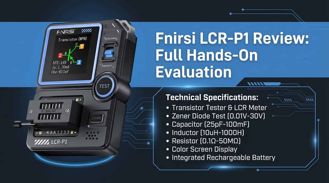
The Fnirsi LCR-P1 positions itself as a “Swiss Army knife” for electronic components—a pocket-sized device that combines a transistor tester, LCR meter, Zener diode tester, and infrared decoder into one compact unit. It targets hobbyists, electronics enthusiasts, and students who need to quickly identify and sort components without hauling around multiple pieces of test equipment.
The device is roughly the size of a credit card and approximately 15mm thick, making it genuinely pocket-portable. It features a modern, attractive design with a 1.44-inch colour display and USB-C charging—a significant aesthetic upgrade over older component testers that often look like bare circuit boards with screens bolted on.
What sets the LCR-P1 apart from basic component testers is its Zener diode testing capability up to 32V. Most standard multimeters and cheap component testers cannot generate sufficient voltage to test Zener diodes properly, making this a genuinely useful feature for anyone working with power supply circuits or voltage regulation.
Order your LCR-P1 today – 2-day UK delivery, 60-day easy returns
Key Specifications of the Fnirsi LCR-P1
Before diving into real-world performance, let me outline what the Fnirsi LCR-P1 claims to measure and test.
Display and Interface
The 1.44-inch TFT colour display (approximately 128×128 pixels) is compact but adequate for displaying component information, schematic symbols, and pinout diagrams. The screen is bright and readable, though the small size means information can feel cramped when displaying multiple parameters.
The interface centres around a large “Test” button for standard measurements, with a dedicated “Zener” button on the side for high-voltage diode testing. A slide switch toggles between transistor testing and infrared decoding modes. The controls are simple and intuitive—insert a component, press test, read the result.
Measurement Ranges
Capacitance: 25 pF to 100 mF (millifarads) Resistance: 0.01 Ω to 50 MΩ Inductance: 10 µH to 1,000 mH (struggles below 3.3 µH) Zener Diodes: 0.01 V to 32 V breakdown voltage Transistors: BJTs, MOSFETs, JFETs, and IGBTs
Supported Component Types
The device automatically identifies and measures:
- BJT transistors (Bipolar Junction Transistors) — measures hFE (current gain) and VBE (base-emitter voltage)
- MOSFETs — measures VT (threshold voltage), CG (gate capacitance), and RDS (drain-source resistance)
- JFETs and IGBTs — basic identification and parameter display
- Capacitors — capacitance value and ESR (Equivalent Series Resistance)
- Resistors — resistance value
- Inductors — inductance value
- Diodes — forward voltage drop and identification
- Zener diodes — breakdown voltage up to 32V
Additional Features
- Infrared decoder — reads NEC protocol remote control signals
- SMD adapter — included daughter card for testing surface-mount components
- ZIF socket — Zero Insertion Force socket for easy component insertion
- External test leads — springy hook clips for testing larger components
Unboxing and First Impressions of the Fnirsi LCR-P1
When the Fnirsi LCR-P1 arrives, you’ll find it reasonably well-packaged. Inside the box, you typically get:
- The LCR-P1 main unit
- SMD testing adapter/daughter card
- External test leads with hook clips
- USB-C charging cable
- User manual
My first impression upon unboxing was positive regarding the device’s appearance. The LCR-P1 has a modern, “sexy” design that looks far more professional than the bare-PCB component testers that dominated this market previously. The build quality is decent with a solid plastic case, though it’s clearly a budget device.
The ZIF (Zero Insertion Force) socket is a thoughtful inclusion. You drop component leads into the numbered holes (1, 2, 3) and lock them with a lever, preventing damage to delicate parts. This is much gentler on components than spring-loaded sockets that can bend leads.
The SMD adapter is genuinely useful. Surface-mount components with unclear markings are notoriously difficult to identify, and this adapter makes testing them straightforward—though you must hold small parts against the gold pads while pressing the test button.
Setup and Calibration Guide
Getting the Fnirsi LCR-P1 up and running is straightforward with minimal setup required.
Basic Component Testing
- Ensure the device is charged via USB-C
- Insert component leads into the numbered slots (1, 2, 3) of the ZIF socket
- Lock the ZIF lever to secure the component
- Press the large “Test” button
- Wait approximately 5 seconds for results
- The device automatically identifies the component type and displays a schematic symbol with pinout
Using the SMD Adapter
For surface-mount components without wire leads:
- Remove the ZIF socket from the main unit
- Attach the included SMD daughter card/adapter
- Place the small component against the gold test pads
- Hold the component firmly in place
- Press the Test button while maintaining contact
- Read the identification and measurements
Zener Diode Testing
Testing Zener diodes requires a specific procedure:
- Insert the diode into the dedicated sockets labelled K (Cathode) and A (Anode)
- Press the dedicated “Zener” button on the side of the unit
- The screen will display “Voltage Regulation Diode”
- Wait for the breakdown voltage reading
Important: Do not use the standard 1-2-3 numbered pins for Zener testing—the device may misidentify the component as a standard diode or capacitor.
Infrared Remote Decoding
- Flip the slide switch from “Transistor” to “IR”
- Point a remote control at the infrared sensor grill
- Press a button on the remote
- The screen displays the received address code and command code (NEC protocol)
External Lead Testing
For components too large for the ZIF socket:
- Plug the provided springy hook clips into the ZIF socket holes
- Clip the hooks onto the component leads
- Press Test as normal
Performance Tests in the Fnirsi LCR-P1 Review
I tested the Fnirsi LCR-P1 across its various functions to understand exactly what this compact device can handle. Here’s what I found.
Capacitor Testing
The LCR-P1 measures capacitance from 25 pF to 100 mF, covering the vast majority of capacitors hobbyists encounter. For basic capacitance values, the device performs adequately—it will tell you if a capacitor is in the right ballpark or completely dead.
ESR measurement limitations:
The device measures ESR (Equivalent Series Resistance), but not using industry-standard methods. Professional equipment uses a 100 kHz sine wave, while the LCR-P1 uses a pulse-based charge/discharge approximation. This means:
- ESR readings may not match manufacturer datasheets
- Results align more closely with 10 kHz test frequency than standard 100 kHz
- Significant variations compared to professional LCR meters (e.g., 0.11 Ω vs 0.01 Ω for the same capacitor)
- Useful for finding dead capacitors, less useful for precise health assessment
The ESR function is best used for sorting obviously bad capacitors rather than detailed analysis. For serious capacitor testing, especially in-circuit, a dedicated tool like the Peak ESR70 is recommended.
Transistor and Semiconductor Testing
Standard silicon transistors: The device identifies BJTs, MOSFETs, JFETs, and IGBTs with reasonable reliability, displaying pinout diagrams and key parameters (hFE, VBE, threshold voltage, etc.).
Germanium transistors: Results are inconsistent. Some tests correctly identified germanium parts with appropriate low VBE readings (around 0.2-0.3V), while other tests produced “garbage information” with incorrect parameters. The device doesn’t explicitly label parts as “germanium.”
Schottky diodes: This is a significant weakness. Multiple tests showed the LCR-P1 misidentifying Schottky diodes as simple resistors or failing to read them entirely. Dual Schottky packages were identified as “two resistances” when older testers like the TC1 identified them correctly.
Thyristors and triacs: The device struggles with these components, often returning “unknown” or misidentifying them.
Zener Diode Testing
This is the LCR-P1’s standout feature. The built-in step-up DC-to-DC converter generates sufficient voltage to test Zener breakdown up to 32V—something most multimeters and budget testers cannot do.
Measured accuracy examples:
- 15V Zener: measured at 14.44V, 14.82V, 14.61V (various tests)
- 18V Zener: measured at 18.24V
- 5.6V Zener: measured at 5.37V
- 5V Zener: measured at 4.44V
These readings are “pretty close” to rated specifications—sufficient for identification and basic verification, though not laboratory-grade precision. The device correctly detects reverse insertion and displays standard forward voltage drop instead.
Resistance and Inductance Testing
Resistance measurement (0.01 Ω to 50 MΩ) performs adequately for general identification and sorting.
Inductance measurement (10 µH to 1,000 mH) works for most common inductors, though the device struggles with values below 3.3 µH.
Infrared Decoding
The IR decoder reads NEC protocol remote controls, displaying address and command codes. This is a niche feature but useful for remote control projects or identifying unknown remotes. Note that it only supports NEC protocol—other infrared protocols won’t be decoded correctly.
Test Speed
The LCR-P1 takes approximately 5 seconds to complete a test. This is noticeably slower than older, cheaper testers like the TC1, which can feel frustrating when sorting through many components.
User Interface and Controls
The button-based interface is simple but effective for the device’s purpose.
Basic Operation
- Test button: Large, central button initiates standard component testing
- Zener button: Side button activates high-voltage Zener testing mode
- IR/Transistor switch: Slide switch toggles between component testing and infrared decoding
- ZIF socket lever: Locks components securely for testing
Display Information
When a component is identified, the display shows:
- Schematic symbol of the component
- Pinout diagram showing which socket holes correspond to which pins
- Measured parameters (capacitance, resistance, hFE, VBE, etc.)
- Component type identification
The 1.44-inch screen can feel cramped when displaying multiple parameters, but information is generally readable.
Firmware Quirks
Several interface issues have been documented:
- The device frequently displays “Unknown/Damaged” when first turned on, requiring a second button press
- Pinout errors for NPN transistors depending on which socket holes are used
- Occasional misidentification requiring retesting
These firmware bugs don’t make the device unusable but can be frustrating.
Battery Life and Portability
True pocket portability is the Fnirsi LCR-P1’s defining characteristic.
The built-in 300mAh lithium battery provides several hours of intermittent testing use. The compact credit card size and 15mm thickness mean it genuinely fits in a pocket or small tool pouch.
Portability advantages:
- Credit card form factor
- Lightweight construction
- USB-C charging from any phone charger or power bank
- LED indicator shows charging status (red) and full charge (green)
- No external power supply needed
The small battery is adequate for field identification work or bench sorting sessions. For extended testing, keep a USB cable handy for top-up charging.
Comparison: Fnirsi LCR-P1 vs Competitors
How does the Fnirsi LCR-P1 stack up against other component testers?
Value for Money
The LCR-P1 offers good value as a multi-function pocket tester, though its firmware issues and accuracy limitations affect the value proposition.
TC1 Component Tester (older/cheaper): Despite being older and less attractive, the TC1 actually outperforms the LCR-P1 in several areas. It correctly identifies Schottky diodes and dual diode packages that the LCR-P1 misreads. ESR readings are closer to professional equipment. Test speed is faster. However, the TC1 cannot test Zener diodes above approximately 12-15V and lacks the modern design and IR decoding. Choose the LCR-P1 for Zener testing and portability; consider the TC1 for better semiconductor identification.
Peak Atlas Component Analysers (professional): Professional testers from Peak offer far superior accuracy, reliability, and component identification. However, they cost significantly more. The LCR-P1 is a hobbyist tool; Peak analysers are professional instruments.
Standard Multimeter: A multimeter can test resistance and basic diode function but cannot identify transistor types, measure capacitance accurately, or test Zener breakdown voltage. The LCR-P1 fills gaps that multimeters cannot address.
Feature Comparison
| Feature | Fnirsi LCR-P1 | TC1 Tester | Peak Atlas |
|---|---|---|---|
| Price | Budget | Very Budget | Professional |
| Zener Testing | Up to 32V | ~12-15V | Varies by model |
| Schottky ID | Poor | Good | Excellent |
| Germanium ID | Inconsistent | Better | Excellent |
| ESR Accuracy | Approximate | Better | Professional |
| Test Speed | ~5 seconds | Faster | Fast |
| Portability | Excellent | Good | Good |
| Display | Colour TFT | Basic LCD | Varies |
| IR Decoding | Yes (NEC) | No | No |
| SMD Adapter | Included | Optional | Varies |
Pros and Cons from the Fnirsi LCR-P1 Review
Pros:
- Genuinely pocket-sized credit card form factor
- Attractive modern design with colour display
- Excellent Zener diode testing up to 32V
- Combines multiple functions (LCR meter, transistor tester, IR decoder)
- SMD adapter included for surface-mount components
- ZIF socket protects component leads
- USB-C charging for convenience
- Automatic component identification with pinout display
- External hook clips for large components
- Good for sorting and identifying unknown parts
Cons:
- Firmware bugs cause occasional misidentification
- Cannot reliably identify Schottky diodes
- Inconsistent results with germanium transistors
- Struggles with thyristors and triacs
- ESR measurement uses approximation, not standard method
- 5-second test time slower than older testers
- “Unknown/Damaged” message on first power-on requires second test
- Pinout errors reported for some transistor configurations
- Small 1.44-inch screen can feel cramped
- Inductance struggles below 3.3 µH
- Not suitable for professional precision work
Typical Use Cases and Who Should Buy the Fnirsi LCR-P1
The Fnirsi LCR-P1 is ideal for:
- Component sorting and identification: Quickly identifying unknown parts from a component bin or salvaged equipment. The automatic identification and pinout display make this straightforward.
- Hobbyist workbench use: General-purpose component testing for Arduino projects, kit building, and electronics tinkering where approximate values are sufficient.
- Zener diode verification: Testing voltage regulation diodes that standard multimeters cannot measure. This is the device’s standout capability.
- SMD component identification: The included adapter makes identifying tiny surface-mount parts with unclear markings much easier.
- Field identification: The pocket-sized form factor allows quick component checks at swap meets, when buying used equipment, or during mobile repair work.
- Students learning electronics: Understanding component types, pinouts, and basic parameters with visual schematic feedback.
- IR remote debugging: Identifying remote control codes for microcontroller projects (NEC protocol only).
Who should look elsewhere:
- Anyone needing reliable Schottky diode identification: The LCR-P1 consistently fails with these components.
- Germanium transistor collectors: Inconsistent identification makes this unsuitable for vintage semiconductor work.
- Professional technicians requiring accuracy: The ESR approximation and firmware bugs make this unsuitable for professional diagnostics.
- High-speed component sorting: The 5-second test time is slow compared to alternatives.
- In-circuit capacitor testing: The device cannot test components while soldered; dedicated ESR meters are needed.
- Anyone needing reliable thyristor/triac testing: The device struggles with these component types.
Common Issues and Troubleshooting Tips
Through my testing and research into user experiences, several common issues emerge with the Fnirsi LCR-P1. Here’s what to watch for and how to address problems.
“Unknown/Damaged” Message on Power-On
The device frequently displays this message when first turned on:
- This is a known firmware bug, not a hardware fault
- Simply press the Test button again
- The device should then function normally
- If the message persists with a known-good component, try repositioning the leads
Schottky Diode Misidentification
The LCR-P1 often identifies Schottky diodes as resistors:
- This is a firmware limitation, not user error
- Try testing in different socket positions
- Accept that this device is unreliable for Schottky identification
- Use an alternative tester (like the TC1) for these components
Inconsistent Transistor Readings
If transistor identification seems wrong:
- Try different socket hole combinations (1-2-3 vs 2-3-1, etc.)
- Pinout errors have been reported depending on insertion position
- Retest multiple times to confirm results
- Cross-reference with datasheet if available
Zener Testing Not Working
If Zener diodes show as standard diodes:
- Ensure you’re using the K (Cathode) and A (Anode) sockets, not the 1-2-3 holes
- Press the dedicated “Zener” button, not the standard Test button
- Check polarity—reverse insertion shows forward voltage drop instead
Slow Test Response
The 5-second test time is normal:
- This is slower than older testers by design
- Wait for the full test cycle to complete
- Don’t press buttons repeatedly during testing
ESR Readings Don’t Match Datasheets
ESR measurements use approximation:
- Results may not align with 100 kHz specifications
- Use readings for relative comparison (good vs bad) rather than absolute values
- For precise ESR testing, use dedicated equipment
IR Decoder Not Reading Remotes
The IR function only supports NEC protocol:
- Many remotes use different protocols
- Ensure the remote is pointed directly at the sensor grill
- The feature won’t work with non-NEC remotes
Accessories and Optional Add-Ons
The Fnirsi LCR-P1 comes with essential accessories included, but a few additions can enhance your experience:
Included accessories:
- SMD testing adapter/daughter card
- External hook clip test leads
- USB-C charging cable
- User manual
Recommended additions:
- Carrying case/pouch: Protect the device and keep accessories together. Budget: £5-10.
- USB power bank: For extended field use beyond the 300mAh battery. Budget: £15-30.
- Component organisation: Small containers or bags for sorting identified components. Budget: £5-15.
- Reference materials: Transistor/component cross-reference guides to verify identifications. Budget: £10-20.
- Backup tester (TC1): For components the LCR-P1 struggles with (Schottky diodes, germanium transistors). Budget: £15-25.
Technical Terms Explained
To help you understand the LCR-P1’s readings, here are key technical terms:
BJT (Bipolar Junction Transistor): A transistor type used for switching or amplifying signals. The tester measures hFE (current gain) and VBE (base-emitter voltage drop, typically 0.6-0.7V for silicon, 0.2-0.3V for germanium).
MOSFET (Metal-Oxide-Semiconductor Field-Effect Transistor): A transistor used for power switching. The device measures VT (threshold voltage), CG (gate capacitance), and RDS (drain-source resistance when on).
ESR (Equivalent Series Resistance): The internal resistance of a capacitor. High ESR indicates an aging or failing capacitor that may still show correct capacitance but performs poorly in circuits.
Zener Diode: Unlike standard diodes, Zeners allow current to flow backward once a specific “breakdown voltage” is reached, making them useful for voltage regulation.
ZIF Socket (Zero Insertion Force): A socket where you drop component leads into holes and lock with a lever, preventing lead damage.
NEC Protocol: A common infrared remote control communication standard. The LCR-P1 only decodes this protocol.
Final Verdict: Is the Fnirsi LCR-P1 Worth It?
After extensive testing, here’s my honest assessment: the Fnirsi LCR-P1 is an attractive, portable multi-function tool that excels at Zener diode testing but suffers from firmware bugs and reliability issues with certain component types.
The Zener testing capability up to 32V is genuinely valuable—most multimeters and budget testers cannot perform this function. If you regularly work with voltage regulation circuits or need to verify Zener diodes, this feature alone may justify the purchase.
The pocket-sized form factor and modern design are appealing. This is a device you’ll actually want to carry, unlike bare-PCB testers that look like unfinished projects.
However, the firmware bugs are frustrating. The inability to reliably identify Schottky diodes—extremely common components—is a significant weakness. Inconsistent germanium transistor identification and the “Unknown/Damaged” power-on glitch suggest the firmware needs improvement.
My recommendation:
If you need Zener diode testing capability and want a pocket-portable component identifier for general hobbyist work, the Fnirsi LCR-P1 offers good value. Accept its limitations with Schottky diodes and specialised semiconductors, and use it for what it does well—sorting components, identifying unknown parts, and testing Zener breakdown voltage.
If you need reliable identification of all semiconductor types, consider keeping an older TC1 tester as a backup for components the LCR-P1 struggles with. For professional precision work, invest in proper test equipment from manufacturers like Peak.
The Fnirsi LCR-P1 is best viewed as a convenient pocket tool for hobbyist component sorting rather than a precision instrument for professional diagnostics.
Where to Buy and Pricing Overview
The Fnirsi LCR-P1 is available from multiple sources:
FNIRSI Oscilloscope Store — Check current pricing for UK customers with dedicated support.
Amazon UK — Typically offers quick delivery with Amazon’s returns policy.
AliExpress — Prices vary; watch for shipping times and import duties.
For UK buyers, check the FNIRSI Oscilloscope Store for current pricing and availability.
[Buy Now – Check Current Price with UK Delivery]
Frequently Asked Questions (FAQ) About the Fnirsi LCR-P1
What components can the Fnirsi LCR-P1 test?
The LCR-P1 can test capacitors (25 pF to 100 mF), resistors (0.01 Ω to 50 MΩ), inductors (10 µH to 1,000 mH), and various semiconductors including BJT transistors, MOSFETs, JFETs, IGBTs, standard diodes, and Zener diodes up to 32V. It also includes an infrared remote decoder for NEC protocol remotes. However, it struggles with Schottky diodes, germanium transistors, and thyristors/triacs.
Is the Zener testing accuracy comparable to a multimeter?
The LCR-P1 is actually more effective than a standard multimeter for Zener testing because it can generate sufficient voltage (up to 32V) to reach breakdown. Most multimeters in diode mode output only a few volts—insufficient for Zener testing. The LCR-P1’s accuracy is “pretty close” to rated specifications (e.g., 15V Zener measured at 14.44-14.82V), which is adequate for identification and verification. The device uses a built-in step-up DC-to-DC converter to generate the necessary high voltage, making it the “best way” to verify Zener regulation voltage without expensive professional equipment.
Can the LCR-P1 identify Schottky diodes?
Unfortunately, no. This is one of the device’s significant weaknesses. Multiple tests showed the LCR-P1 misidentifying Schottky diodes as simple resistors or failing to read them entirely. Dual Schottky packages were identified as “two resistances” when older testers correctly identified them. If you regularly work with Schottky diodes, consider a backup tester like the TC1.
How accurate is the ESR measurement?
The ESR measurement should be considered approximate rather than precise. The LCR-P1 uses a pulse-based charge/discharge method rather than the industry-standard 100 kHz sine wave. This means readings may not match manufacturer datasheets and can vary significantly from professional LCR meters. The ESR function is useful for identifying obviously bad capacitors but not for detailed health analysis.
Why does it show “Unknown/Damaged” when I turn it on?
This is a known firmware bug. The device frequently displays this message on initial power-up even with no component inserted or with a known-good component. Simply press the Test button again, and the device should function normally. This annoyance doesn’t indicate a hardware fault.
How long does a test take?
Each test takes approximately 5 seconds to complete. This is noticeably slower than older budget testers like the TC1. Wait for the full test cycle before pressing buttons again.
Can I test SMD components?
Yes, the LCR-P1 includes an SMD adapter daughter card. Remove the ZIF socket, attach the adapter, place the surface-mount component against the gold test pads, hold it firmly in place, and press Test. You must maintain contact throughout the test cycle.
What is the battery life?
The 300mAh lithium battery provides several hours of intermittent testing use. For extended sessions, keep a USB-C cable handy for charging. The LED indicator shows red while charging and green when fully charged.
Does it work with all infrared remotes?
No, the IR decoder only supports NEC protocol remotes. Many remotes use different protocols that the LCR-P1 cannot decode. If your remote isn’t recognised, it likely uses a different communication standard.
How does it compare to the older TC1 tester?
The TC1 actually outperforms the LCR-P1 in several areas: better Schottky diode identification, more accurate ESR readings, and faster test times. However, the TC1 cannot test Zener diodes above approximately 12-15V and lacks the modern design, colour display, and IR decoding. Choose based on which features matter most for your work.
Have more questions about the Fnirsi LCR-P1? Looking for the best deal for UK customers?