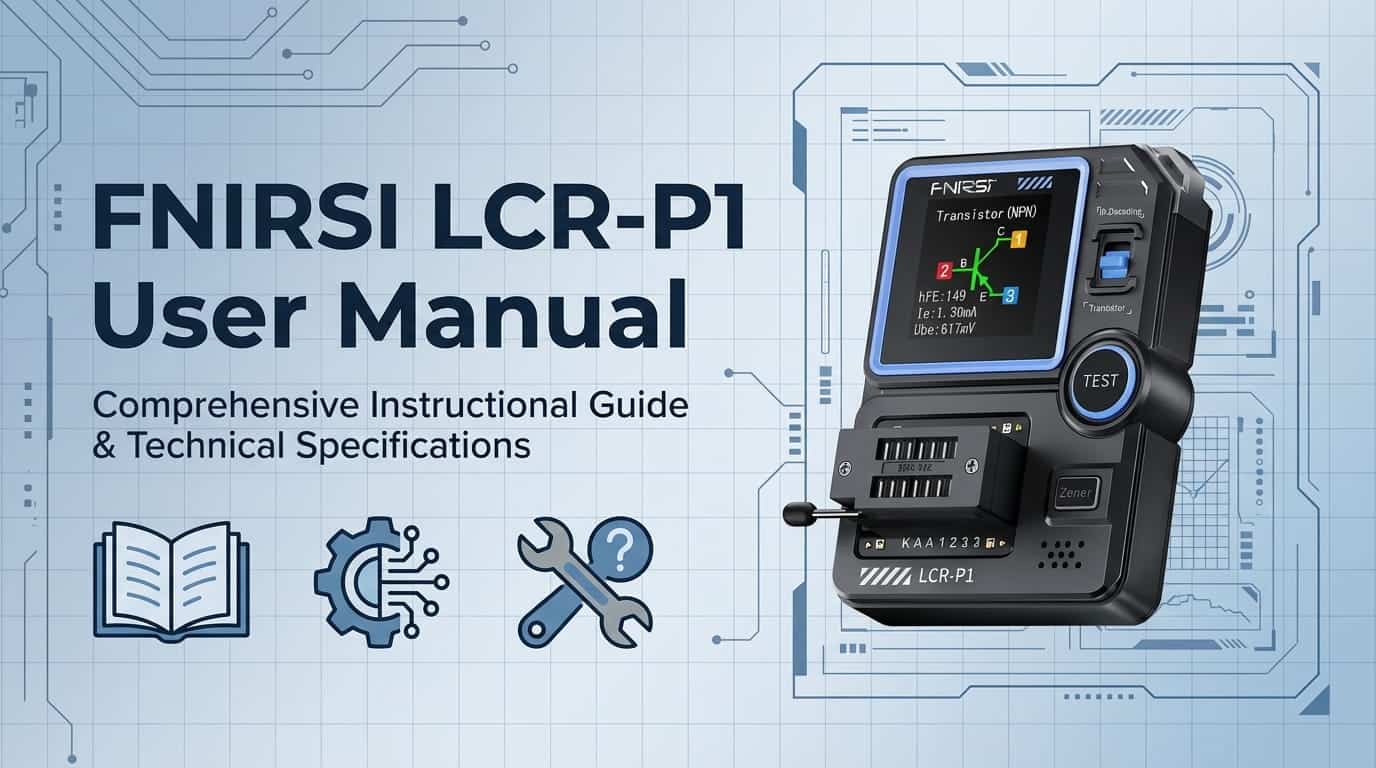
FNIRSI LCR-P1 User Manual
NOTICE TO USERS
- This manual provides detailed instructions on how to use the product, precautions, and relevant information. Please read the manual carefully before using the product to ensure optimal performance.
- Do not use the instrument in flammable or explosive environments.
- Dispose of used batteries and discarded instruments according to national or local regulations; they should not be disposed of with household waste.
- If there are any quality issues with the instrument or if you have any questions about its use, please contact “FNIRSI” online customer service or the manufacturer. We will resolve your issue promptly.
1. PRODUCT INTRODUCTION
The FNIRSI LCR-P1 Transistor Tester is a high-precision, multifunctional electronic testing device designed specifically for electronic engineers, technicians, and electronics enthusiasts. This device is intended for detecting and analyzing the performance and characteristics of semiconductor components such as:
- Transistors
- Diodes
- Triodes
- Field-Effect Transistors (FETs)
Key Features:
Advanced Testing Capabilities:
- Equipped with a color screen for clear display
- Multi-parameter measurement of various components
- Automatically identifies component type and pin arrangement
- Simplified operation process
- Enhanced testing efficiency
Component Detection:
- Transistors (NPN/PNP)
- Diodes (standard and Zener)
- MOSFETs (N-channel/P-channel)
- JFETs
- IGBTs
- SCRs (Silicon Controlled Rectifiers)
- Capacitors
- Resistors
- Inductors
- Battery voltage testing
- Infrared remote control decoding
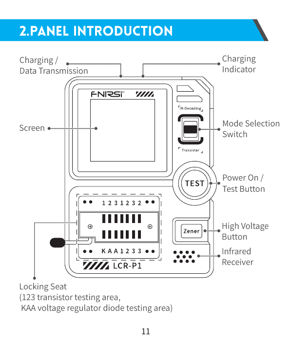
2. PANEL INTRODUCTION
Order your LCR-P1 today – 2-day UK delivery, 60-day easy returns
Device Components:
Front Panel:
- Screen Display
- 1.44-inch color LCD display
- Clear parameter readout
- Real-time measurement display
- Locking Seat (Testing Area)
- 1-2-3 Transistor Testing Area
- K-A-A Voltage Regulator Diode Testing Area
- Secure component insertion with locking mechanism
- Power On / Test Button
- Short press: Power on or initiate test
- Long press: Power off
- High Voltage Button (Zener Button)
- Activates Zener diode testing mode
- High voltage testing capability up to 32V
- Mode Selection Switch
- Toggle between standard testing mode and infrared decoding mode
- Infrared Receiver
- Located on top of device
- Receives infrared signals for remote control decoding
Rear Panel:
- Charging Port (Type-C)
- USB Type-C charging and data transmission
- 5V/1A charging specification
- Charging Indicator LED
- Illuminates during charging
- Turns off when fully charged
3. PARAMETER INTRODUCTION
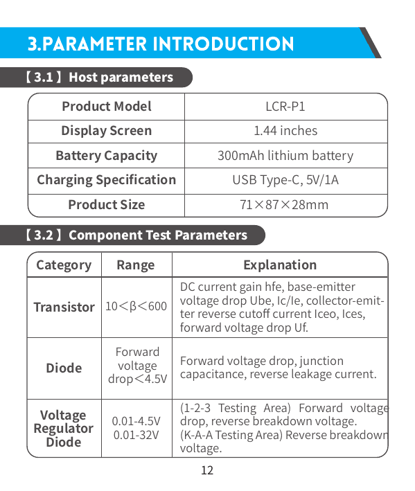
【3.1】 Host Parameters
| Specification | Value |
|---|---|
| Product Model | LCR-P1 |
| Display Screen | 1.44 inches color LCD |
| Battery Capacity | 300mAh lithium battery |
| Charging Specification | USB Type-C, 5V/1A |
| Product Dimensions | 71×87×28mm |
| Weight | Compact and portable design |
【3.2】 Component Test Parameters
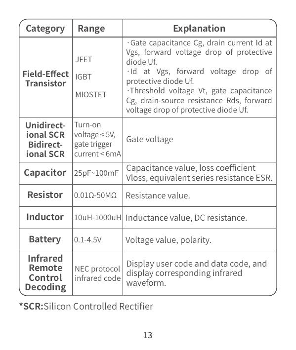
Transistor Testing
| Parameter | Range | Measured Values |
|---|---|---|
| DC Current Gain | 10 < β < 600 | hfe (amplification factor) |
| Base-Emitter Voltage | – | Ube voltage drop |
| Collector/Emitter Current | – | Ic/Ie ratio |
| Reverse Cutoff Current | – | Iceo, Ices |
| Protection Diode | – | Forward voltage drop Uf |
Diode Testing
| Parameter | Range | Measured Values |
|---|---|---|
| Forward Voltage Drop | < 4.5V | Voltage drop measurement |
| Junction Capacitance | – | Capacitance value |
| Reverse Leakage Current | – | Leakage measurement |
Voltage Regulator Diode (Zener) Testing
| Test Area | Range | Measured Values |
|---|---|---|
| 1-2-3 Testing Area | 0.01-4.5V | Forward voltage drop, reverse breakdown voltage |
| K-A-A Testing Area | 0.01-32V | Reverse breakdown voltage (high voltage mode) |
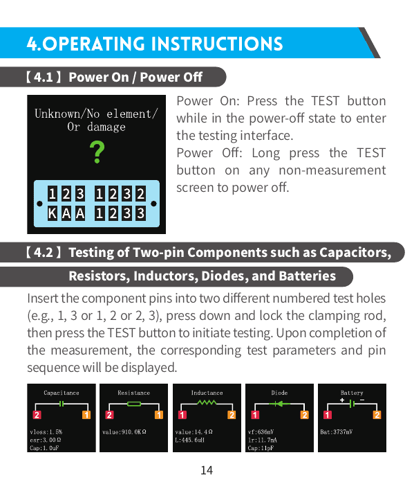
Field-Effect Transistor (FET) Testing
JFET (Junction FET):
- Gate capacitance (Cg)
- Drain current (Id) at specified Vgs
- Forward voltage drop of protection diode (Uf)
IGBT (Insulated Gate Bipolar Transistor):
- Drain current (Id) at specified Vgs
- Forward voltage drop of protection diode (Uf)
MOSFET (Metal-Oxide-Semiconductor FET):
- Threshold voltage (Vt)
- Gate capacitance (Cg)
- Drain-source resistance (Rds)
- Forward voltage drop of protection diode (Uf)
SCR Testing (Silicon Controlled Rectifier)
| Type | Range | Measured Values |
|---|---|---|
| Unidirectional SCR | Gate trigger voltage < 5V | Gate voltage |
| Bidirectional SCR | Gate trigger current < 6mA | Gate voltage |
Passive Component Testing
Capacitor:
- Range: 25pF ~ 100mF
- Measured Values:
- Capacitance value
- Loss coefficient (Vloss)
- Equivalent Series Resistance (ESR)
Resistor:
- Range: 0.01Ω ~ 50MΩ
- Measured Values: Resistance value
Inductor:
- Range: 10uH ~ 1000uH
- Measured Values:
- Inductance value
- DC resistance
Battery Testing
- Range: 0.1V ~ 4.5V
- Measured Values:
- Voltage value
- Polarity (positive/negative)
Infrared Remote Control Decoding
- Protocol: NEC infrared code
- Display:
- User code
- Data code
- Corresponding infrared waveform
4. OPERATING INSTRUCTIONS
【4.1】 Power On / Power Off
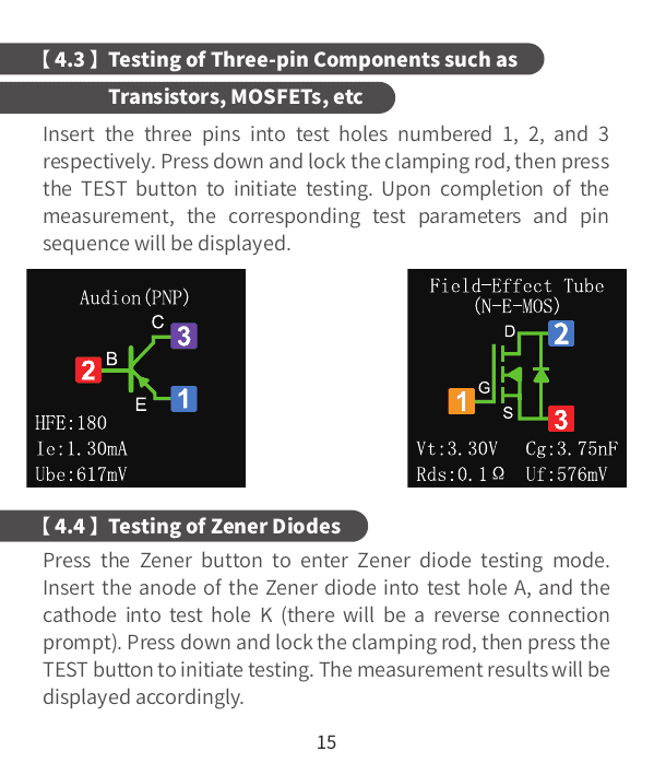
Power On:
- Press the TEST button while in the power-off state to enter the testing interface
Power Off:
- Long press the TEST button on any non-measurement screen to power off the device
【4.2】 Testing Two-Pin Components
(Capacitors, Resistors, Inductors, Diodes, Batteries)
Procedure:
- Insert Component Pins
- Insert component pins into two different numbered test holes
- Available combinations: 1-3, 1-2, or 2-3
- Lock the Component
- Press down and lock the clamping rod to secure the component
- Start Testing
- Press the TEST button to initiate testing
- View Results
- Upon completion, the display shows:
- Component type
- Measured parameters
- Pin sequence/polarity
- Upon completion, the display shows:
Example Components:
- Capacitors: Displays capacitance, ESR, loss coefficient
- Resistors: Displays resistance value
- Inductors: Displays inductance and DC resistance
- Diodes: Displays forward voltage drop, junction capacitance
- Batteries: Displays voltage and polarity
【4.3】 Testing Three-Pin Components
(Transistors, MOSFETs, etc.)
Procedure:
- Insert Three Pins
- Insert the three component pins into test holes numbered 1, 2, and 3 respectively
- Pin order doesn’t matter – the tester auto-detects
- Lock the Component
- Press down and lock the clamping rod to secure the component
- Start Testing
- Press the TEST button to initiate testing
- View Results
- Upon completion, the display shows:
- Component type (NPN, PNP, N-MOS, P-MOS, etc.)
- Pin identification (Base, Collector, Emitter or Gate, Drain, Source)
- All relevant electrical parameters
- Upon completion, the display shows:
Tested Components:
- Bipolar Junction Transistors (BJT): NPN, PNP
- MOSFETs: N-channel, P-channel
- JFETs: N-channel, P-channel
- IGBTs
- SCRs (Thyristors)
【4.4】 Testing Zener Diodes
Procedure:
- Enter Zener Mode
- Press the Zener button (high voltage button) to enter Zener diode testing mode
- Insert Component
- Insert the anode of the Zener diode into test hole A
- Insert the cathode into test hole K
- ⚠ If reversed, the device will display a reverse connection warning
- Lock the Component
- Press down and lock the clamping rod
- Start Testing
- Press the TEST button to initiate testing
- View Results
- Display shows:
- Zener breakdown voltage (reverse voltage)
- Forward voltage drop
- Component confirmation
- Display shows:
Note: Zener testing mode can measure breakdown voltages up to 32V
【4.5】 Infrared Decoding
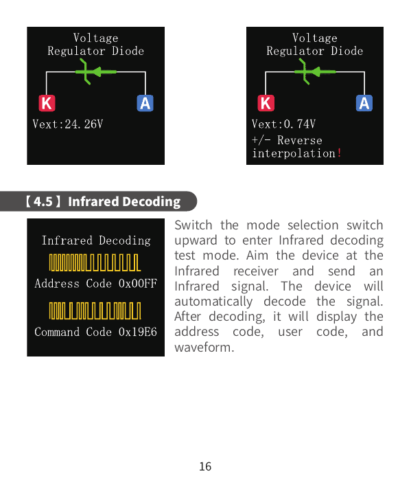
Procedure:
- Enter Infrared Mode
- Switch the mode selection switch upward to enter infrared decoding test mode
- Send Infrared Signal
- Aim your remote control at the infrared receiver on top of the device
- Press any button on the remote control
- Automatic Decoding
- The device will automatically decode the infrared signal
- View Results
- After decoding, the display shows:
- Address code
- User code
- Infrared waveform (visual representation)
- After decoding, the display shows:
Supported Protocol:
- NEC infrared protocol
Applications:
- Testing TV remotes
- Testing air conditioner remotes
- Testing universal remotes
- Debugging custom infrared devices
5. FIRMWARE UPDATE
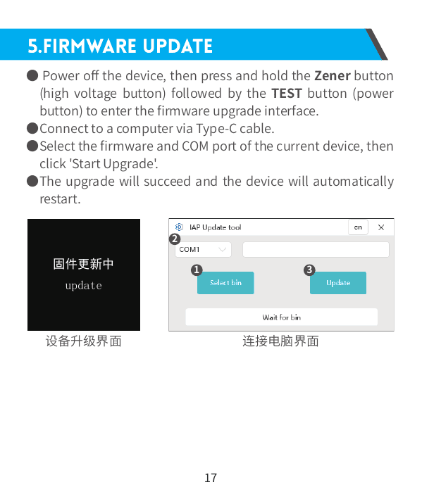
Firmware Upgrade Procedure:
Step 1: Enter Upgrade Mode
- Power off the device completely
- Press and hold the Zener button (high voltage button)
- While holding Zener, press the TEST button (power button)
- Continue holding both until the firmware upgrade interface appears
Step 2: Connect to Computer
- Connect the device to your computer using a Type-C cable
- Device will be recognized as a serial port
Step 3: Select Firmware and Port
- Open the firmware upgrade software on your computer
- Select the firmware file you downloaded from the official website
- Select the correct COM port for your device
Step 4: Start Upgrade
- Click “Start Upgrade” button
- Monitor the upgrade progress on screen
- Do not disconnect during the upgrade process
Step 5: Complete
- Upon successful upgrade, the device will automatically restart
- New firmware version will be active
⚠ Important Notes:
- Download firmware only from official FNIRSI website
- Ensure device has sufficient battery charge before upgrading
- Do not disconnect USB cable during upgrade
- If upgrade fails, repeat the process or contact customer support
6. PRECAUTIONS
⚠ Important Safety Warnings:
1. Capacitor Testing – Discharge Warning
- When measuring capacitors without prior discharge, sparks may occur at the moment of insertion and locking
- The device will automatically discharge the capacitor upon insertion
- This function serves as a safety measure to prevent accidents
- ⚠ RECOMMENDED: Always manually discharge capacitors before testing for proper and safe usage
2. Battery Insertion Warning
- During non-measurement processes, the 1-2-3 locking interface is in a conductive state
- NEVER insert batteries directly into the 1-2-3 test holes without activating test mode
- This could cause short circuits or damage
3. Measurement Range Limitations
- Testing component parameters outside the specified range may result in:
- Incorrect identification of component types
- Inaccurate readings
- Display of “Unknown” or error messages
- Always verify component specifications are within device capabilities before testing
4. Component Handling
- Handle sensitive components (MOSFETs, CMOS devices) with proper ESD precautions
- Ensure component pins are clean and free of oxidation
- Insert components fully into test holes for accurate readings
5. Power Supply
- Use only the specified Type-C USB charging cable
- Charging specification: 5V/1A
- Do not use fast chargers or non-standard power adapters
6. Environmental Conditions
- Do not use in flammable or explosive environments
- Keep device away from moisture and extreme temperatures
- Store in a dry, cool place when not in use
7. Maintenance
- Regularly clean test hole contacts to maintain accuracy
- Keep the locking mechanism free of debris
- Replace battery when device shows low power warnings
8. Disposal
- Dispose of used batteries according to local regulations
- Do not discard with household waste
- Recycle electronic waste responsibly
7. CONTACT US

Customer Support Promise:
Any FNIRSI user who contacts us with questions will receive:
- ✅ A satisfactory solution to their issue
- ✅ An extra 6 months warranty extension to thank you for your support!
We have created an interesting community for FNIRSI users. Welcome to contact FNIRSI staff to join our community and connect with other electronics enthusiasts!
Contact Information:
Company Name:
Shenzhen FNIRSI Technology Co., LTD.
Address:
West of Building C, Weida Industrial Park
Dalang Street, Longhua District
Shenzhen, Guangdong, China
Telephone:
0755-28020752
Website:
www.fnirsi.cn
Business Inquiries:
business@fnirsi.com
Equipment Service & Technical Support:
service@fnirsi.com
Download Resources:
Visit our official website to download:
- 📄 Latest user manuals
- 💻 PC software and applications
- 🔧 Firmware updates
- 📱 Mobile apps
- 📹 Video tutorials
- 📊 Technical documentation
TECHNICAL SPECIFICATIONS SUMMARY
Device Capabilities:
| Component Type | Measurement Range | Key Parameters |
|---|---|---|
| Transistors | β: 10-600 | hfe, Ube, Ic/Ie, Iceo, Ices, Uf |
| Diodes | Vf < 4.5V | Forward drop, capacitance, leakage |
| Zener Diodes | 0.01-32V | Breakdown voltage, forward drop |
| MOSFETs | Various | Vt, Cg, Rds, Id, Uf |
| JFETs | Various | Cg, Id at Vgs, Uf |
| IGBTs | Various | Id at Vgs, Uf |
| SCRs | Vgate < 5V | Gate voltage, trigger current |
| Capacitors | 25pF-100mF | C, ESR, Vloss |
| Resistors | 0.01Ω-50MΩ | Resistance value |
| Inductors | 10uH-1000uH | L, DC resistance |
| Batteries | 0.1-4.5V | Voltage, polarity |
| Infrared | NEC protocol | User code, data code, waveform |
TROUBLESHOOTING GUIDE
Common Issues and Solutions:
Issue: Device won’t power on
- Check battery charge level
- Connect Type-C charger and wait 5 minutes
- Try pressing TEST button for 3 seconds
Issue: “Unknown” component display
- Verify component is not damaged
- Check if component parameters are within measurement range
- Clean component pins and test holes
- Ensure proper insertion and locking
Issue: Inconsistent readings
- Clean test hole contacts
- Verify component is securely locked
- Check for oxidized or dirty component pins
- Perform baseline calibration if available
Issue: Capacitor sparking during test
- This is normal for charged capacitors
- Always discharge large capacitors manually before testing
- Use appropriate safety measures
Issue: Can’t decode infrared signal
- Ensure mode switch is in infrared position
- Check if remote uses NEC protocol
- Aim remote directly at receiver
- Replace remote batteries if weak
Issue: Firmware upgrade fails
- Check USB cable connection
- Ensure correct COM port selected
- Verify firmware file is for LCR-P1 model
- Try different USB port on computer
- Contact customer support if problem persists
QUICK REFERENCE GUIDE
Button Functions:
- TEST Button (Short Press): Power on / Start test
- TEST Button (Long Press): Power off
- Zener Button: Enter Zener diode high voltage test mode
- Mode Switch (Up): Infrared decoding mode
- Mode Switch (Down): Standard component testing mode
Test Hole Configurations:
- 1-2-3 Holes: Standard component testing (2-pin and 3-pin)
- K-A-A Holes: Zener diode high voltage testing
LED Indicators:
- Charging LED On: Device is charging
- Charging LED Off: Fully charged or not connected
WARRANTY INFORMATION
Standard Warranty:
- Manufacturer’s warranty period as specified at purchase
- Covers manufacturing defects and material faults
Extended Warranty:
- Contact customer support for an additional 6 months warranty extension
- Simply reach out with any questions or support needs
Warranty Exclusions:
- Physical damage from misuse
- Damage from liquid exposure
- Unauthorized modifications or repairs
- Normal wear and tear
Thank you for choosing FNIRSI LCR-P1 Transistor Tester!
This device is designed to provide accurate, reliable component testing for electronics professionals and enthusiasts. Please read this manual carefully and refer to it whenever needed. Keep this manual in a safe place for future reference.
For the latest updates, firmware, and support, visit: www.fnirsi.cn